FlexTRAK OH Material Handler Manual.pdf - 第83页
FlexTRAK-OH Material Handli ng System IOM Manual Installation © 2023 Nordson C orporation 3-33 Table 3- 11 Sample Read ings Measured from Each Finger Items I/O Threshold force (gram) Actual force (gram) Claw 1 – Finger 1…
FlexTRAK-OH Material Handling System IOM Manual Installation
3-32 © 2023 Nordson Corporation
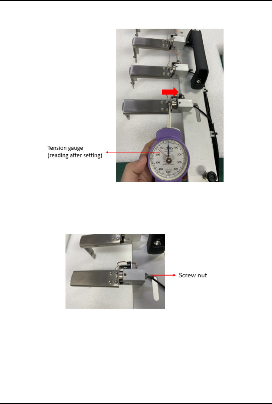
4. Return the claw jam to its original position (Figure 3-55) and then take the reading directly
from the gauge (reading shown by red needle).
Figure 3-55 Claw Jam Sensitivity Adjustment 3
5. If the tension gauge does not show a proper reading, use a screw driver to loosen or tighten
the screw nut (Figure 3-56).
6. Repeat Step 1 through Step 5 until correct reading is obtained.
Figure 3-56 Screw Nut
NOTE The above settings are applicable for both loader and unloader claws. Specification
values are within the range of 80 to 200 grams. Actual settings used should correspond to
maximum allowable force to prevent damage to the strips. Settings should also be
uniform across all buffer lanes. Refer to Table 3-11 for sample readings measured from
each finger.

FlexTRAK-OH Material Handling System IOM Manual Installation
© 2023 Nordson Corporation 3-33
Table 3-11 Sample Readings Measured from Each Finger
Items I/O
Threshold
force (gram)
Actual force
(gram)
Claw 1 – Finger 1 I007.00
100
170
Claw 1 – Finger 2 I007.01 110
Claw 1 – Finger 3 I007.02 140
Claw 1 – Finger 4 I007.03 110
Claw 1 – Finger 5 I007.04 140
Claw 1 – Finger 6 I007.05 120
Claw 1 – Finger 7 I007.06 100
Claw 1 – Finger 8 I007.07 N/A
Claw 2 – Finger 1 I009.00 150
Claw 2 – Finger 2 I009.01 140
Claw 2 – Finger 3 I009.02 140
Claw 2 – Finger 4 I009.03 100
Claw 2 – Finger 5 I009.04 120
Claw 2 – Finger 6 I009.05 110
Claw 2 – Finger 7 I009.06 100
Claw 2 – Finger 8 I009.07 N/A
N/A: Current used lane quantity of the conversion kit is 7 lanes.
FlexTRAK-OH Material Handling System IOM Manual Installation
3-34 © 2023 Nordson Corporation
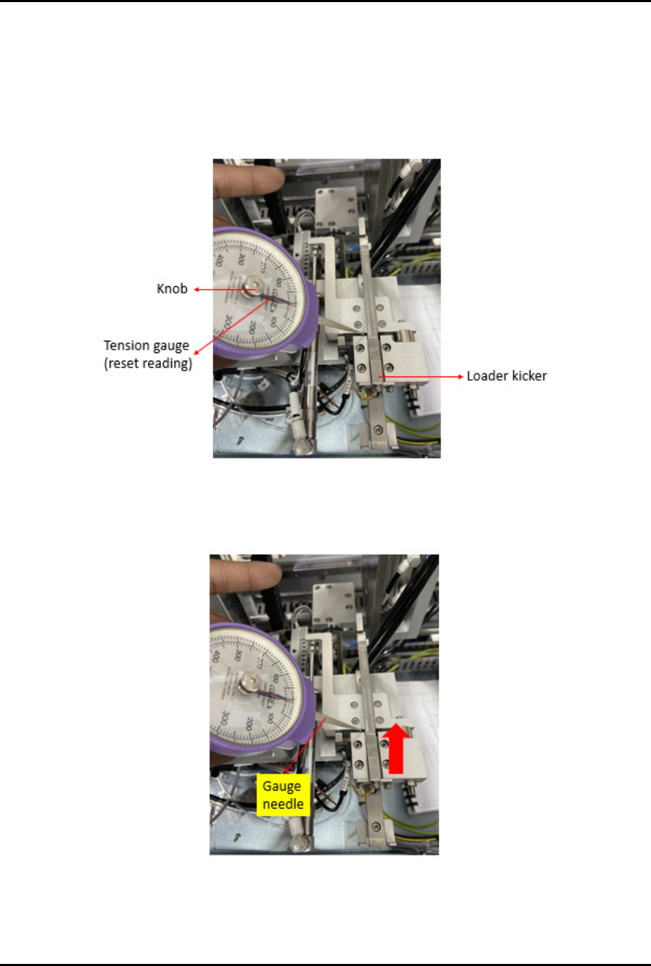
3.7.9 Loader Kicker Sensitivity Adjustment
1. Prepare a tension gauge (Figure 3-57).
a. Ensure the tension gauge is in good condition.
b. Reset both needles to the default position by rotating the knob in the clockwise or
counterclockwise direction.
Figure 3-57 Loader Kicker Sensitivity Adjustment 1
2. Put the gauge needle on the loader kicker then pull it in the direction as indicated by the red
arrow (Figure 3-58).
Figure 3-58 Loader Kicker Sensitivity Adjustment 2