FlexTRAK OH Material Handler Manual.pdf - 第36页
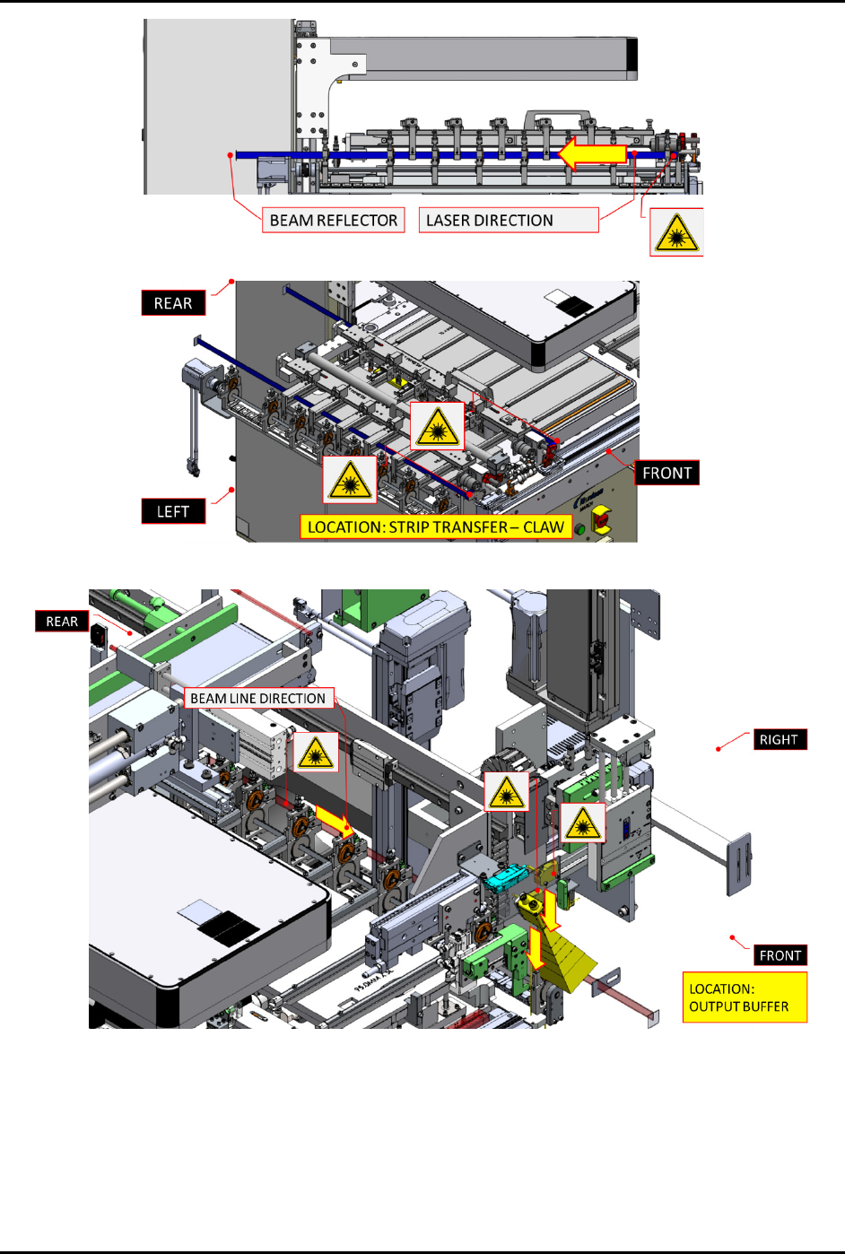
FlexTRAK-OH Material Handli ng System IOM Manual Safety 2-6 © 2023 Nordson C orporation Figure 2-3 Laser Beam Location 2 - Claw Mod ule Figure 2-4 Laser Beam Location 3 - Output Buffer Lane
FlexTRAK-OH Material Handling System IOM Manual Safety
© 2023 Nordson Corporation 2-5
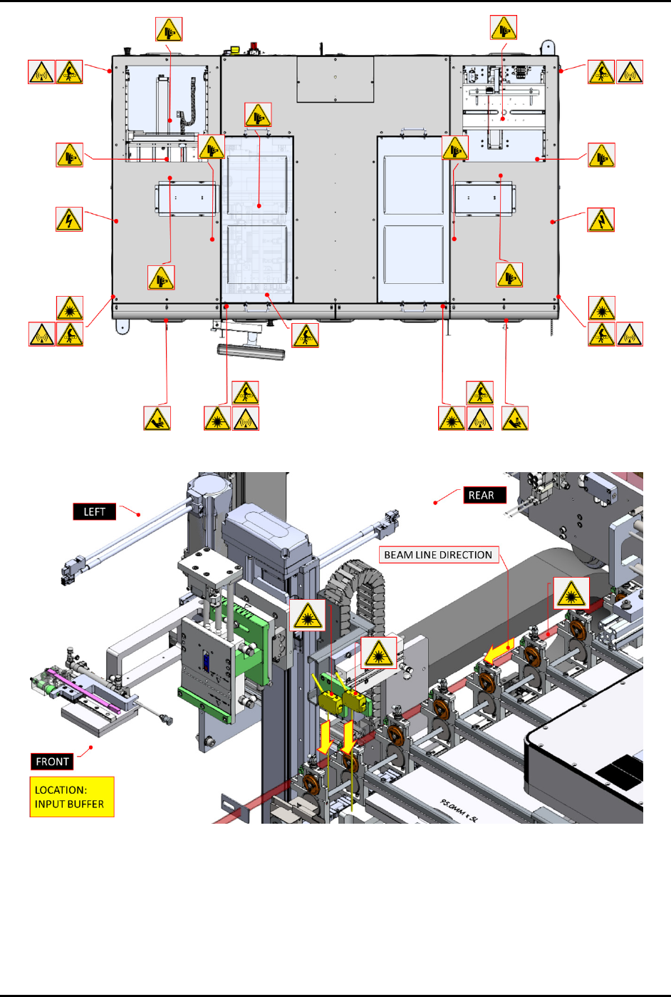
Figure 2-1 FlexTRAK-OH Overall Safety Hazard Label Locations (Top View)
Figure 2-2 Laser Beam Location 1 – Input Buffer Lane
FlexTRAK-OH Material Handling System IOM Manual Safety
2-6 © 2023 Nordson Corporation
Figure 2-3 Laser Beam Location 2 - Claw Module
Figure 2-4 Laser Beam Location 3 - Output Buffer Lane
FlexTRAK-OH Material Handling System IOM Manual Safety
© 2023 Nordson Corporation 2-7
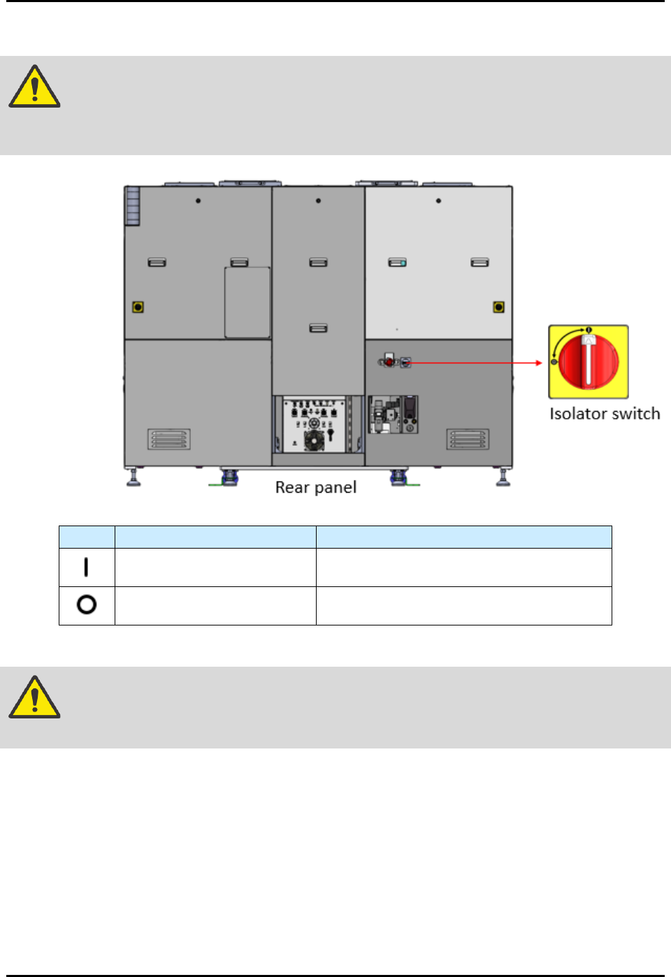
2.10 Isolator Switch
DANGER! The isolator switch (Figure 2-5) only isolates electrical energy from facilities to
connect with machine local electrical components. Electrical energy is still
present inside the isolator switch’s electrical input or incoming points.
Sign
Operation Mode
Description
Twist handle to the power on
position.
Energizes the machine's local electrical
components.
Twist handle to the power off
position.
Cuts off the electrical energy from the
facilities to the machine's local components.
Figure 2-5 Isolator Switch
WARNING! Always apply the LOTO kit to the isolator switch when electrical energy
isolation is in progress for maintenance or troubleshooting tasks.