FlexTRAK OH Material Handler Manual.pdf - 第44页
FlexTRAK-OH Material Handli ng System IOM Manual Safety 2-14 © 2023 Nordson C orporation 2.16 Light Tower Stat us Lights The FlexTRAK - OH Material Handler includ es two PLC - controlled light t ower s that constantly sh…
FlexTRAK-OH Material Handling System IOM Manual Safety
© 2023 Nordson Corporation 2-13
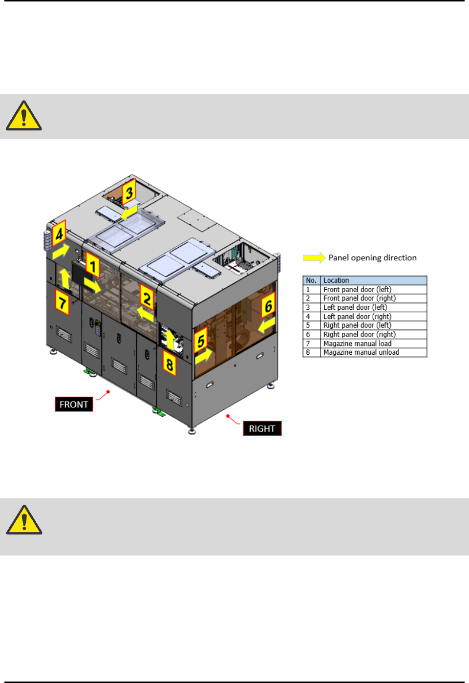
2.15 Safety Interlocks
Electromechanical interlocks prevent personnel from being exposed to high RF voltages, mechanical
hazards, and RF radiation hazards that are present while the FlexTRAK-OH Material Handler is in
operation. They function using a switch that trips when a door is opened. When the switch is tripped, the
FlexTRAK-OH Material Handler and reaction chamber cease movement.
WARNING! When these interlocks are activated, the electrical power remains ON.
There are total of eight (8) interlocks on FlexTRAK-OH Material Handler (Figure 2-11).
Figure 2-11 Safety Interlock Location
Once the interlock switch is triggered (sense guard door is open), it will cause the safety relay to cut off
machine servo motor power. See 8.6 System Block Diagram.
WARNING! Do not bypass the interlock switch that guards the access door in automated
operation mode.
Once the current process sequences have been stopped, no reset is possible until the guard door has been
closed. In order to resume operation, close the open guard door and press the RESET button.
FlexTRAK-OH Material Handling System IOM Manual Safety
2-14 © 2023 Nordson Corporation
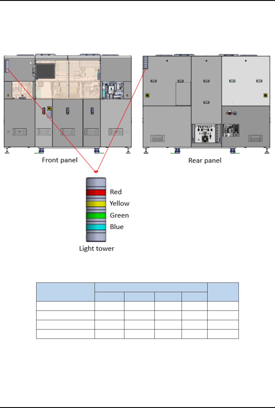
2.16 Light Tower Status Lights
The FlexTRAK-OH Material Handler includes two PLC-controlled light towers that constantly show the
status of the current machine status (Figure 2-12). Light tower color indications are described in
Table 2-2.
Figure 2-12 Light Tower
Table 2-2 Light Tower Status Lights
Machine Status
LED Color
Buzzer
Sound
Red
Yellow
Green
Blue
Running
Solid
Off
Auto mode
Solid
Off
Manual mode
Solid
Off
Alarm
Solid
On
FlexTRAK-OH Material Handling System IOM Manual Safety
© 2023 Nordson Corporation 2-15
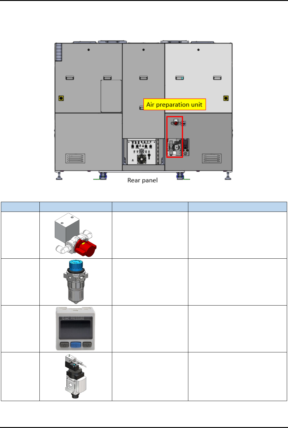
2.17 Air Preparation Unit
The Air Preparation Unit is shown in Figure 2-13.
Item
Part Illustration
Function
Description/Operation Mode
Manual
shut-off
valve
Isolates pneumatic
energy to machine local
components and
integrated equipment
Incoming air state:
SUP: air is supplied
EXH: air is isolated
OFF (0): power is disconnected
Air
pressure
regulator
Increase/decrease air
pressure
Increase when turning knob in "+"
direction.
Decrease when turning knob in
"-" direction.
Air
pressure
gauge
Indicates incoming
compressed air pressure
with configurable upper
and lower limits of air
pressure.
Press related button to configure
the settings. Refer OEM manual:
IMM_xSE30_TFI48GB-A.pdf for
further information.
Soft start
switch
Gradually increases air
pressure when
energized.
Gradually raise the compressed
air pressure to the machine and
automatically shut-off/exhaust the
compressed air.
Controlled by the machine system
(PLC I/O signal).
Figure 2-13 Air Preparation Unit