1OM-1064-002.pdf - 第10页
Contents Page 9.4 Procedure for Nozzle Batch Storage ......................................... 4-23 9.5 Procedure for Continuous Operation (T est on Nozzle Attachment and Storage Operations) .............. 4-23 10. P .C.…

Contents
Page
9910-001 7 Tg0246-PM-OP
7.4 Possible Operations during Automatic Operation ..................... 2-66
7.5 Emergency Stop ........................................................................ 2-67
7.5.1 Cause and Symptom of Emergency Stop ........................... 2-67
7.5.2 Reset and Start Procedure from Emergency Stop .............. 2-68
8. Shut-Down Operation (End of Production) ...................................... 2-69
Section 3 Automatic Operation Menus ........................................ 3- 1
1. Hierarchical Structure of Automatic Operation Displays ................. 3- 2
2. AUTO OPN MODE (PLACEMENT) Display .................................... 3- 3
3. AUTO OPN SUB-MENU Display ..................................................... 3- 7
4. SEMI-AUTOMATIC OPERATION ................................................... 3-13
4.1 Normal Step Designation (Without Non-Placement Steps) ....... 3-13
4.2 Selection of WARM or COLD Start Operation ........................... 3-16
4.3 Warm Start ................................................................................ 3-17
5. Operation Mode ............................................................................... 3-19
5.1 AUTOMATIC FEEDER AXIS ADJUSTMENT MODE Display ... 3-20
5.2 OVERALL TACT-TIME REDUCTION Display ........................... 3-21
5.3 RECOG MONITOR DISPLAY MODE Display ........................... 3-23
5.4 P.E.C. MANUAL ALIGNMENT MODE Display .......................... 3-25
5.5 ALTERNATE MODE Display ..................................................... 3-26
5.6 COMPONENT MISSING CHECK MODE Display ..................... 3-31
6. RECOVERY OPN. TEACHING OPN. Display ................................ 3-32
6.1 PATTERN PROGRAM EDIT Display ........................................ 3-33
6.2 COMPONENT LIBRARY Display .............................................. 3-34
6.3 COMP. CARRIAGE DATA EDIT Display
(Simplified Packaging Direction Change Function)................... 3-35
6.4 FEEDER (B) OFFSET Display .................................................. 3-41
7. Tray Pick-Up Matrix (Option) ........................................................... 3-42
Section 4 Manual Mode Menus ...................................................... 4- 1
1. Hierarchical Structure of Manual Mode Displays ............................ 4- 2
2. MANUAL MODE Display ................................................................. 4- 3
3. Program Change ............................................................................. 4- 5
4. Product Change .............................................................................. 4- 6
4.1 Selection of Set-Up Menus and Overall Set-Up Operation ....... 4- 6
4.2 Manual Set-Up at Each Display (Display for Each Device) ....... 4- 8
4.3 Overall Automatic Set-Up Function Interlinked with
Program Change ....................................................................... 4-10
5. Zeroing Operation ........................................................................... 4-11
6. Manual Subsystem Operation ......................................................... 4-13
7. Manual Axis Operation .................................................................... 4-14
8. Manual Transfer Operation ............................................................. 4-18
9. Manual Nozzle Change Operation .................................................. 4-22
9.1 Procedure for Nozzle Stocker Opening/Closing Operation ....... 4-22
9.2 Procedure for Nozzle Attachment.............................................. 4-22
9.3 Procedure for Nozzle Storage ................................................... 4-23

Contents
Page
9.4 Procedure for Nozzle Batch Storage ......................................... 4-23
9.5 Procedure for Continuous Operation
(Test on Nozzle Attachment and Storage Operations).............. 4-23
10. P.C.B. Support Pins Set-Up Mode ................................................. 4-26
9910-001 8 Tg0246-PM-OP
1. Safety Precaution “Safety Requirements”
0304-002 9 Tg0246-PM-OP
1. Safety Precaution “Safety Requirements”
This section describes "1.1 Caution of Pre-Installation", "1.2 Precautions be-
fore Operation", "1.3 Precautions during Operation", "1.4 Precautions
in Maintenance" and "1.5 Other Precautions". Please read the following
items carefully before using the machine to ensure smooth operation.
1.1 Caution of Pre-Installation
If the machine is installed in unsatisfactory environmental condition, it will mal-
function due to damage or breakdown made to bear on the machine. To avoid
this, make preparations to install the machine as follows.
• The primary power source must be prepared on the local source.
Voltage: 200 ± 20 V AC, 3-Phase
Maximum Power Consumption: Approx. 7kVA
• Our service personnel will connect the primary power source.
When any person other than our service personnel must connect the primary
power source, consult our marketing depatment or sales agency beforehand.
• If the machine is scheduled to be transferred to another place, please contact
our sales division or agency beforehand.
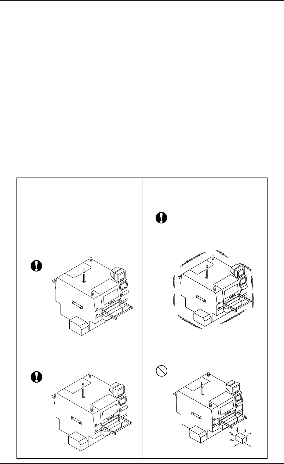
• Select a place solid enough to support the
weight of the machine.
Ref.: It is recommended that the ma-
chine should be installed on the
first floor.
When the machine has to be
installed on a floor other than the
first one, please consult our sales
personnel or agency for details.
• Avoid any place that vibrates severely.
• Environmental temperature must be 20 ±
10°C, humidity 30% to 80%, and dew
condensation must be avoided.
• Ensure that the selected place is free from
electric noises.