1OM-1064-002.pdf - 第194页
5. Operation Mode 9910-001 3-25 Tg0246-PM-OP 5.4 P .E.C. MANUAL ALIGNMENT MODE Display • Described below is how to perform the P .E.C. manual alignment operation after a P .E.C. recognition error has occurred. When the […
5. Operation Mode
9910-001 3-24 Tg0246-PM-OP
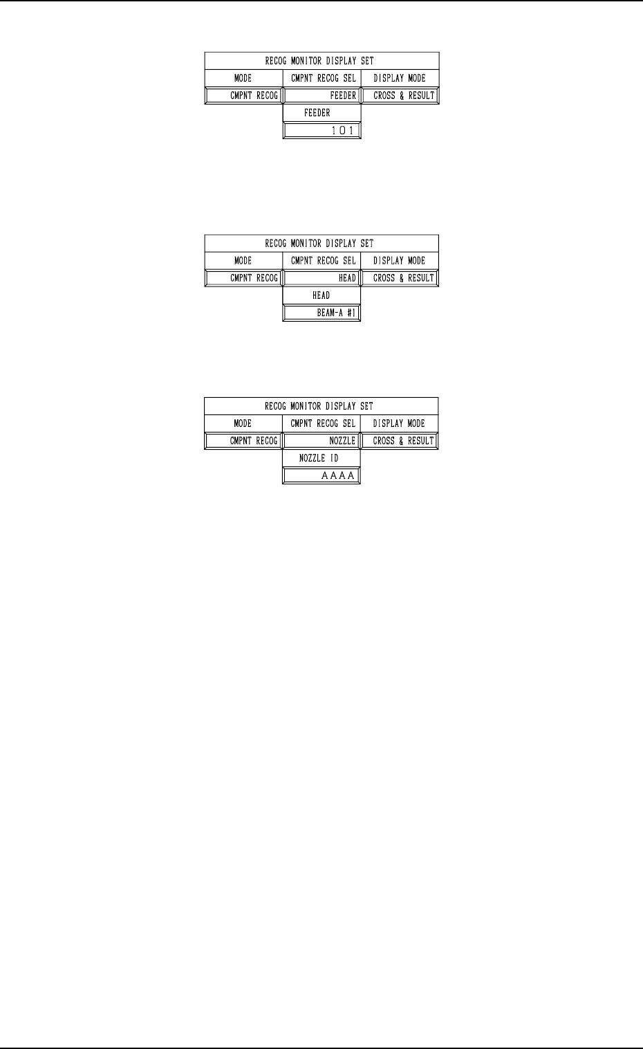
• When “FEEDER” is set in the data box, specify the feeder No.
Fig. 3.10-3
• When “HEAD” is set in the data box, specify the head No. “BEAM-A #1”,
“BEAM-A #2”, “BEAM-B #1”, or “BEAM-B #2”.
Fig. 3.10-4
• When “NOZZLE” is set in the data box, specify the nozzle ID.
Fig. 3.10-5
DISPLAY MODE
Specify the requirements which the displayed result should be based on
only for the component recognition function.
Options: “CROSS”, “CROSS & RESULT”, “OFF”
It is recommended that “CROSS” should be set in the data box.
5. Operation Mode
9910-001 3-25 Tg0246-PM-OP
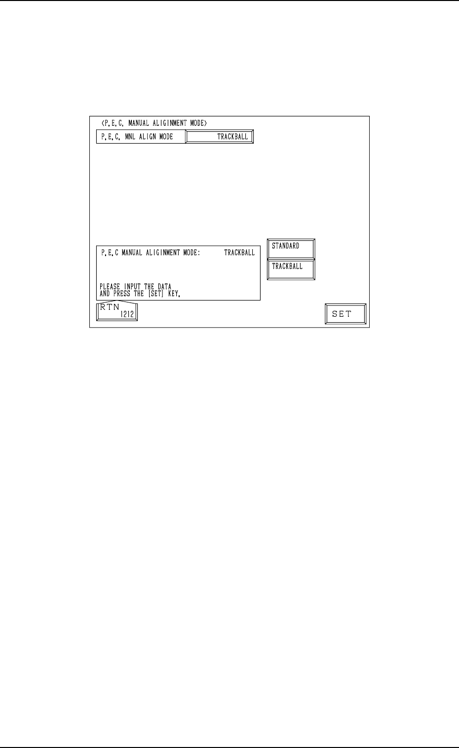
5.4 P.E.C. MANUAL ALIGNMENT MODE Display
• Described below is how to perform the P.E.C. manual alignment operation
after a P.E.C. recognition error has occurred.
When the [P.E.C. MANUAL ALIGNMENT MODE] key is pressed at the
“OPERATION MODE” display, the following display appears on the screen.
Fig. 3.11
When a P.E.C. recognition error has occurred, the fiducial mark position must
be specified through manual alignment operation. “STANDARD” or
“TRACKBALL” can be selected as a manual alignment mode.
STANDARD : When one of the direction keys is selected on the touch screen
(“MANUAL ALIGNMENT” display) and the [MOVE] but-
ton is pressed, the captured image of the component can be
aligned manually.
TRACKBALL : The mark position (a view on the recognition monitor) can
be specified and aligned manually through track ball opera-
tions.
5. Operation Mode
Fig. 3.12
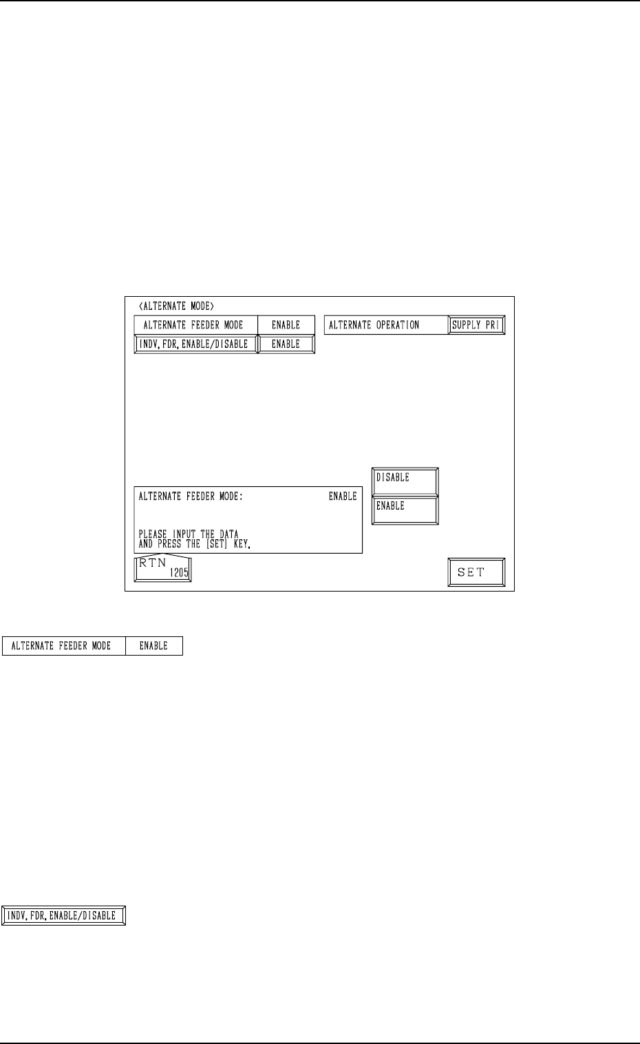
“ALTERNATE FEEDER MODE”
“ENABLE”
This appears in the text box when “ON” is set in the “MODE”
data field of the label “ALTERNATE FDR.” at the “COM-
PONENT DATA” display. (Hierarchical Sequence: “DATA
EDIT” Display → “PATTERN PROGRAM” Display →
“PATTERN PROGRAM EDIT” Display → “COMPONENT
DATA” Display → “COMPONENT DATA EDIT” Display)
“DISABLE”
This appears in the text box when “OFF” is set in the
“MODE” data field of the label “ALTERNATE FDR.” at
the “COMPONENT DATA” display.
[INDV. FDR. ENABLE/DISABLE] Key
When this key is pressed, the “INDIVIDUAL FDR EN-
ABLE/DISABLE” display (Fig. 3.13) appears on the screen.
5.5 ALTERNATE MODE Display
• This display allows the operator to determine whether or not the alternate
feeder mode should be used.
Every time a component shortage error occurs at a feeder, the alternate feeder
mode enables the component pick-up position to be shifted automatically to
another alternative one (specified as the substitute), making it possible for
the machine to perform the operation continuously.
When the [ALTERNATE MODE] key is pressed at the “OPERATION MODE”
display, the following display appears on the screen. (Hierarchical Sequence:
“AUTO OPN. MODE <PLACEMENT>” Display → “AUTO OPN. SUB-
MENU” Display → “OPERATION MODE” Display)
9910-001 3-26 Tg0246-PM-OP