1OM-1064-002.pdf - 第34页
2. Specifications 9910-001 1-4 Tg0246-PM-OP Exam pl e : T o c or r ect t he p osi ti ona l devia t ion c over ing t he whole ar ea of P C B ( P C B Over a ll C or r ect ion) T o impr ove r ecognit ion a cc u r a cy, p u …
9910-001 1-3 Tg0246-PM-OP
2. Specifications
2. Specifications
1. Model Name TIM-5100
2. PCB Flow
Direction and
Transfer
Reference
PCB Flow Direction from Left to Right or vice versa
(Easy-to-Change Function)
3. Applicable PCB Size : 50 × 50 to 460 × 381 mm
(Four Corners : R1 to R1.5 mm)
Thickness : 0.3 to 5.0 mm
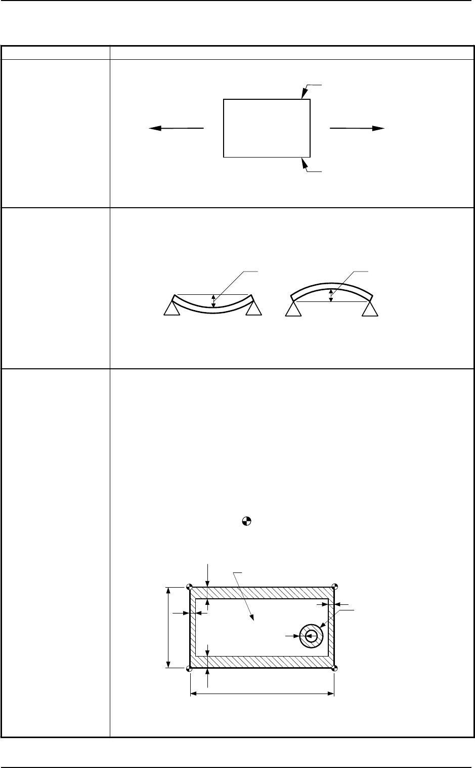
Warpage : 0.2 mm or less per 50 mm
Max. 1.5 Max. 1.5
Unit : mm
Mass : Max. 2 kg (completed PCB)
Note :
A test is required for greater warpage, depending on the material and
shape of the PCB being used.
4. PCB Position
Correction
Method and
Reference Point
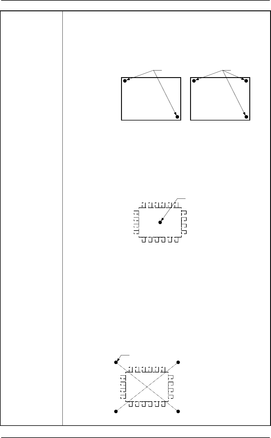
Position Correction Method: PEC Recognition
• By recognizing the fiducial marks using the PEC camera, positional
deviation covering the whole area of PCB and expansion of the printed
patterns on PCB can be corrected.
• To correct the positional deviation covering the whole area of PCB,
fiducial marks must be put on two or three places of PCB (2 fiducial
marks required for each unit PCB of a multi-unit PCB).
• To correct the positional deviation of component placement points, put
one to two fiducial marks on the PCB In this case, it is recommended that
two fiducial marks be located symmetrically such that the center of
gravity (the center of the fiducial marks) becomes the center of the
component placement point.
Note : The center of the mark is the reference point.
The reference point differs depending on the contents of the
specifications. Consult our sales personnel for details
.
4.5
50 ~ 381
4.5
1
1
50
~
460
Front Side of Machine
Range where a fiducial mark can be put
Hole, etc
1
Unit : mm
(Front Side of Machine)
PCB
Transfer Reference
(Longer Side) based on
“Front Reference”
Transfer Reference
(Longer Side) based
on “Rear Reference”
2. Specifications
9910-001 1-4 Tg0246-PM-OP
Example :
To correct the positional deviation covering the whole area of PCB (PCB
Overall Correction)
To improve recognition accuracy, put fiducial marks diagonally on two places of
PCB when the 2-point recognition mode is selected. In the case of 3-point
recognition mode, put two fiducial marks diagonally and one fiducial mark close to
one of the remaining corners.
PCB
Fiducial Mark
PCB
Fiducial Mark
Example 1 :
To correct the positional deviation of component placement points
(1-point recognition)
Put a fiducial mark on the center of component placement point or
a desired point around the center.
Recommended Position: Center of Component Placement Point
•
This position is effective when the positional deviation covering the whole
area of PCB is corrected.
When the PCB overall correction operation is performed, the theta (angle)
correction is also made. The fiducial mark described here is used to correct
the placement position.
Fiducial Mark
Example 2 :
To correct the component placement point
(2-point recognition)
Put fiducial marks on the desired two points around the center of
component placement point.
Recommended Position : Point Symmetry
It is recommended that two points (fiducial marks)
should be located symmetrically on both sides of the
center of the placement position.
(A-A'/B-B')
•
These fiducial marks are used to correct the component position and the
theta (angle).
The 2-point recognition is effectively to correct deviated and distorted part
of the printing patterns.
Fiducial Mark
A
A'B
B'
2. Specifications
9910-001 1-5 Tg0246-PM-OP
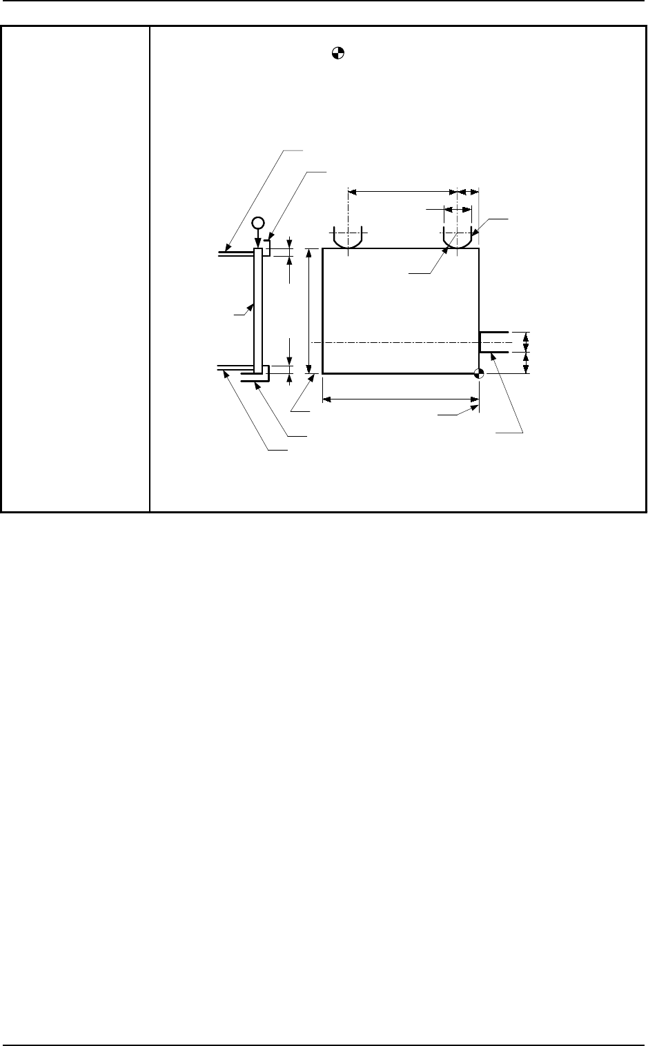
PCB Clamping: Mechanical Clamping
Note : The center of the mark is the reference point.
The reference point and plane differ depending on the contents of
the specifications. There is no change in the distances between the
reference point and the PCB stopper and between the reference
plane and the Y pusher. Consult our sales personnel for details.
11
PCB
PCB Stopper
(either one of the right and left stoppers)
Clamp Plate on Fixed Side
Fixed Chute
Movable Chute
Clamp Plate on Movable Side
R20
27
58
×
7
10
6
50
t
o
381
50
t
o
460
Y Pusher
Reference
Plane
Reference
Plane
2.5 2.5
Unit : mm