1OM-1064-002.pdf - 第32页
1. Scope of Machine This latest and most powerful machine in new generation is provided with an image recognition device which uses 2-beam, 4-head, and 4-camera system and can place standard components (from 1005 compone…

Section 1
Scope
9910-001 1-1 Tg0246-PM-OP

1. Scope of Machine
This latest and most powerful machine in new generation is provided with an
image recognition device which uses 2-beam, 4-head, and 4-camera system and
can place standard components (from 1005 components to deform components
such as QFP, BGA/CSP, SOP, connectors, and switches of 55 × 55 mm and
square components) packaged in tapes, stick, trays, etc.
Small and light DD (Direct Drive) motors are used for the placement heads
(called “DD heads” hereinafter), enabling the highly accurate θ correction. The
2-beam cooperative movement also made it possible to achieve the tact time of
approx. 0.46 seconds per component.
9910-001 1-2 Tg0246-PM-OP
1. Scope of Machine
9910-001 1-3 Tg0246-PM-OP
2. Specifications
2. Specifications
1. Model Name TIM-5100
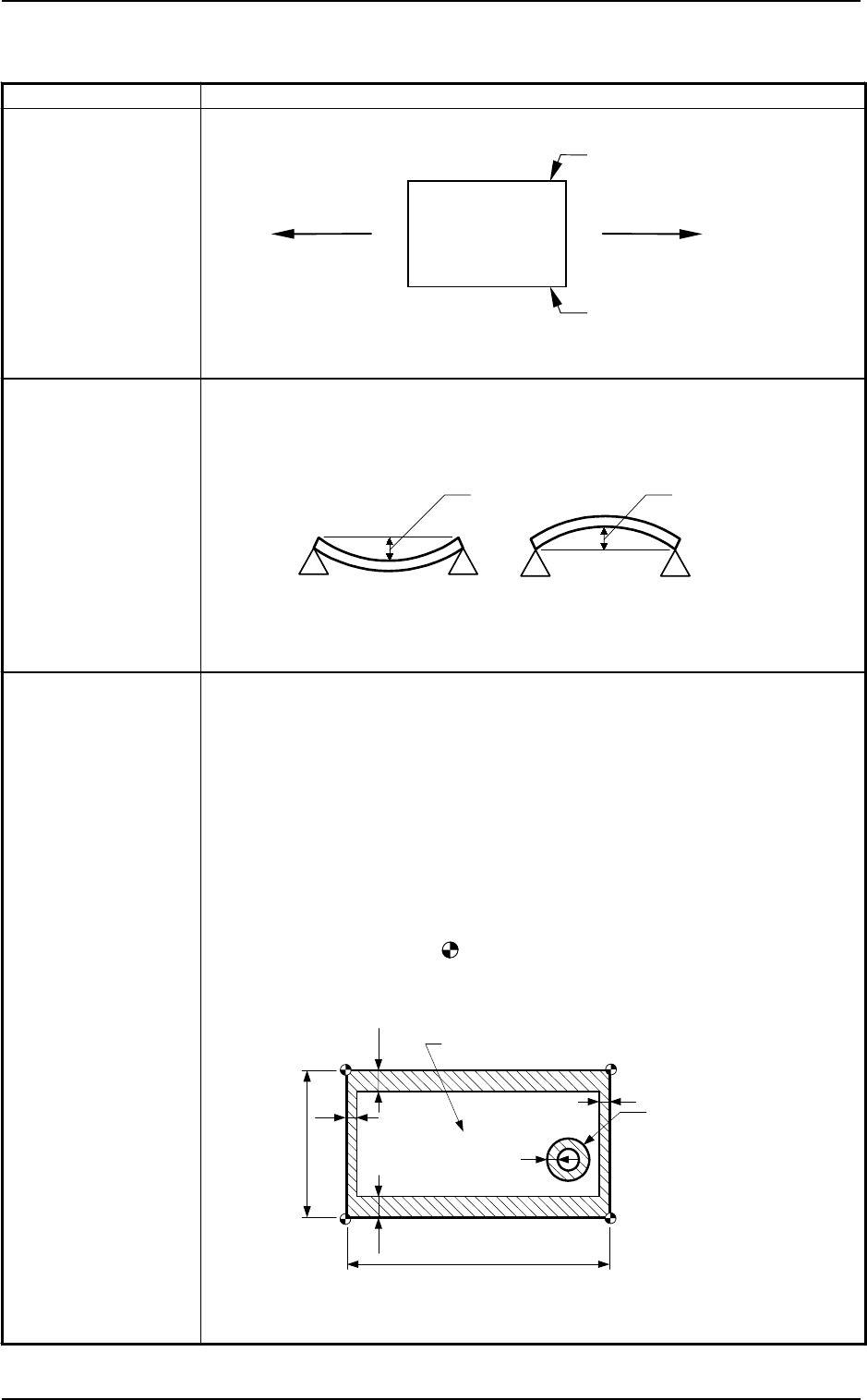
2. PCB Flow
Direction and
Transfer
Reference
PCB Flow Direction from Left to Right or vice versa
(Easy-to-Change Function)
3. Applicable PCB Size : 50 × 50 to 460 × 381 mm
(Four Corners : R1 to R1.5 mm)
Thickness : 0.3 to 5.0 mm
Warpage : 0.2 mm or less per 50 mm
Max. 1.5 Max. 1.5
Unit : mm
Mass : Max. 2 kg (completed PCB)
Note :
A test is required for greater warpage, depending on the material and
shape of the PCB being used.
4. PCB Position
Correction
Method and
Reference Point
Position Correction Method: PEC Recognition
• By recognizing the fiducial marks using the PEC camera, positional
deviation covering the whole area of PCB and expansion of the printed
patterns on PCB can be corrected.
• To correct the positional deviation covering the whole area of PCB,
fiducial marks must be put on two or three places of PCB (2 fiducial
marks required for each unit PCB of a multi-unit PCB).
• To correct the positional deviation of component placement points, put
one to two fiducial marks on the PCB In this case, it is recommended that
two fiducial marks be located symmetrically such that the center of
gravity (the center of the fiducial marks) becomes the center of the
component placement point.
Note : The center of the mark is the reference point.
The reference point differs depending on the contents of the
specifications. Consult our sales personnel for details
.
4.5
50 ~ 381
4.5
1
1
50
~
460
Front Side of Machine
Range where a fiducial mark can be put
Hole, etc
1
Unit : mm
(Front Side of Machine)
PCB
Transfer Reference
(Longer Side) based on
“Front Reference”
Transfer Reference
(Longer Side) based
on “Rear Reference”