1OM-1064-002.pdf - 第41页
2. Specifications 9910-001 1-11 Tg0246-PM-OP Fiducial Marks Through Hole s Shapes Pad Marks Size 0.5 to 2.0 mm Material • Copper Leaf (Au and Ni plating possible but m irror surfaces cannot be used.) • Solder-Plated Mark…
2. Specifications
9910-001 1-10 Tg0246-PM-OP
Camera for Extra Large Visual Field
Front Lighting Recognition
2.0 × 1.2 to 46 × 46 mm
Batch
Back Lighting Recognition
2.0 × 1.2 to 36 × 36 mm
Divided
Front Lighting Recognition Max. 55 × 55 mm
Note
Minimum Lead Pitch : 0.5 mm
Minimum Ball Diameter : φ 0.5 mm
Minimum Ball Pitch : 0.7 mm
Camera for Large Visual Field
Front Lighting Recognition
2.0 × 1.2 to 46 × 34 mm
Batch
Back Lighting Recognition
2.0 × 1.2 to 36 × 35 mm
Divided
Front Lighting Recognition Max. 55 × 55 mm
Note
Minimum Lead Pitch : 0.4 mm
Minimum Ball Diameter : φ 0.4 mm
Minimum Ball Pitch : 0.55 mm
Camera for Small Visual Field
Front Lighting Recognition
1.0 × 0.5 to 23 × 15 mm
Batch
Back Lighting Recognition
1.0 × 0.5 to 23 × 15 mm
Divided
Front Lighting Recognition Max. 55 × 55 mm
Minimum Lead Pitch : 0.3 mm
Minimum Ball Diameter : φ 0.19 mm
Minimum Ball Pitch : 0.27 mm
Applicable
Component Sizes
Note : In the case of the connector , this recognition can
be applied to Max. 150 × 26 mm.
Ref. : Two types of cameras (four cameras in total) can
be installed on Beams A and B.
Photoimage Front Lighting System
(Direct Recognition of Component by Front Lighting)
Back Lighting System
(Recognition by Component Silhouette)
25. Component
Recognition
Notes : (a) The cameras are automatically selected according to the shape
and size of a component.
(b) The cameras (option) are to be selected by the customer. As a
standard combination of cameras, four large view cameras are
recommended. Consult our sales personnel for details.
Visual Field Approx. 16 × 12 mm
Ref. : One camera is installed on Beam A and the other
on Beam B.
Window Size 1.0 × 1.0 to 5.0 × 5.0 mm
Recognition
(Processing) Time
Approx. 0.15 second/mark
(including the reading time of the image)
Photoimage Front Lighting System
(Recognition of Fiducial Mark by Front Lighting)
(“Normal” or “Reverse” can be selected for each mark.)
26. P.E.C.
Recognition
Notes : (a) The above recognition time will be obtained when the window
size is “3 × 3 mm” and a fiducial mark size is “φ 1.0 mm”. The
recognition time changes according to the window size, a fiducial
mark size, etc.
(b) Time of X/Y beam movement is included in the actually
measured recognition time.
2. Specifications
9910-001 1-11 Tg0246-PM-OP
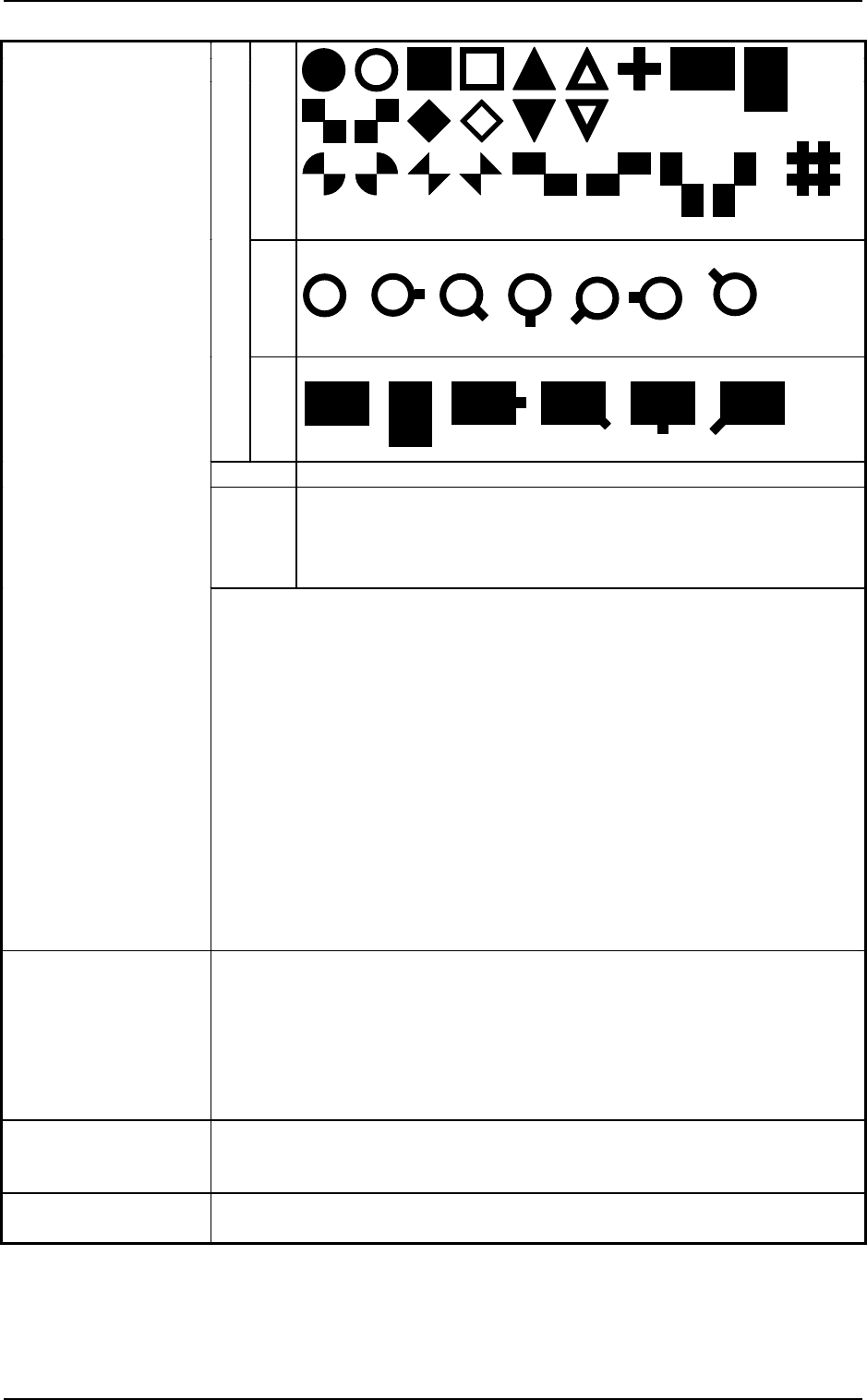
Fiducial Marks
Through
Hole
s
Shapes
Pad Marks
Size 0.5 to 2.0 mm
Material
• Copper Leaf (Au and Ni plating possible but mirror surfaces
cannot be used.)
• Solder-Plated Marks (Consult our sales personnel for details.)
• Solder Leveler (Consult our sales personnel for details.)
27. Fiducial Marks
Notes : (a) A through hole or a pad mark should have only one land which
is directed in increments of 45°. Consult our sales personnel for
details.
(b) The fiducial mark should make ample contrast with the
surroundings.
(c) A test may be required when the fiducial mark cannot be
recognized because of the extreme warpage of the PCB.
(d) Anything like a pattern similar to a fiducial mark should not
exist in the designated window. If exists, it may cause a false
recognition. Also the shape (a cutout, a punched hole) of the
PCB, the light reflected from a structure, or the light from the
external elements may sometimes interfere with the recognition.
Consult our sales personnel for details.
(e) Consult our sales personnel for details if you require additional
information.
28. Specifications of
Automatic Setup
Function
When a program change is made, the PCB transfer conveyor width and the
PCB backup pin’s up/down movement are automatically set up.
Minimum Unit of Movement
PCB Transfer Conveyor Width : 0.1 mm
(Resolution : 0.0025 mm/pulse)
PCB Backup Pin Up/Down Movement : 0.01 mm
(Resolution : 0.00048075 mm/pulse)
29. Power Supply 200 ± 20 V AC, 3-Phase, 50/60Hz
Connected to the power supply unit (3-phase 4-wire system)
(One of the four wires is used as a ground wire.)
30. Maximum Power
Consumption
Approx. 7 kVA
Others
Others
(Under Development)
9910-001 1-12 Tg0246-PM-OP
2. Specifications
Supply
Pressure
0. 49 to 0.69 MPa (5 to 7 kgf/cm
2
)
Dry and Clean Air (Moisture, oil, and dust are removed.)
Set
Pressure
0.49 MPa (5 kgf/cm
2
)
31. Air Supply
• Dray and Clean Air
Moisture : Dew Point −17℃ or lower (Atmospheric Pressure)
Oil : 0.1 mg/m
3
or less (ANR)
Dust : Solid Material 0.01 µm or less
32. Air Consumption Approx. 20 l/min (ANR)
33. Vacuum Pressure −93 kPa (70 cmHg)
34. Environmental
Condition
Temperature : 20 ± 10°C
Humidity : 30 to 80% (Avoid dew condensation.)
35. Basic Dimensions 1,700 (width) × 2,228 (depth, excluding the safety bar) × 1,565 mm (height)
Notes : (a) The height becomes 2,100 mm when the light tower is included.
(b) The depth becomes 3,118 mm when the safety bar is included.
2,420 kg (only the main body section)
Note : The mass changes depending on the type of feeders to be installed.
Mass of Options (For Reference)
Name Mass (kg)
Tape Feeder The mass depends on
feeder types.
Stick Feeder (Vibratory) Approx. 6.5/feeder
Multi-Layer Tray Feeder Approx. 180/feeder
Note : The mass related to components is not included.
36. Basic Mass