1OM-1064-002.pdf - 第118页
3. Confirmation and Procedure of Power Supply Pressure Switch 0.39 MPa (4 kgf/cm 2 ) Air Blowing Pressure 0.015 MPa (0.15 kgf/cm ) Supplied Air: 0.49 to 0.69 MPa (5 to 7 kgf/cm ) Main Pressure 0.49 MPa (5 kgf/cm ) Main V…
2. Hierarchical Structure of Operation Displays
Foreground Colors Background Colors
Keys related to
“AUTO OPN MODE”
Blue
Green
Keys related to
“MANUAL MODE”
Blue Light Green
Keys related to
“DATA EDIT”
Blue Light Blue
Keys related to
“SPECIAL SEL.”
Blue Light Yellow
Keys related to
“MACHINE SET-UP”
Blue Light Gray
9910-001 2-19 Tg0246-PM-OP
2.4 Touch Screen Keys
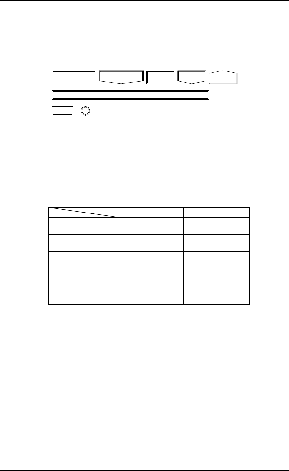
The following frame icons are used as keys to distinguish between the simple
indication sections (format field, title field, explanation, etc.) and the keys.
(1) Keys are enclosed by the following double frames.
Fig. 2.16
(2) When a colored key is selected, the current display is changed to another
one.
The colors used for keys significantly related to the hierarchical branches
(AUTO OPN MODE, MANUAL MODE, DATA EDIT, SPECIAL SEL.,
and MACHINE SET-UP) of the “MAIN MENU” display are selected
such that the operator can conceptualize an operation type through the
colors.
Table 2.2
(3) Uncolored keys can be selected. When such a key is selected, it is col-
ored. Another touch screen key, etc., must usually be pressed after the
selection.
3. Confirmation and Procedure of Power Supply
Pressure Switch 0.39 MPa
(4 kgf/cm
2
)
Air Blowing Pressure
0.015 MPa (0.15 kgf/cm
)
Supplied Air: 0.49 to 0.69 MPa
(5 to 7 kgf/cm
)
Main Pressure 0.49 MPa
(5 kgf/cm
)
Main Valve
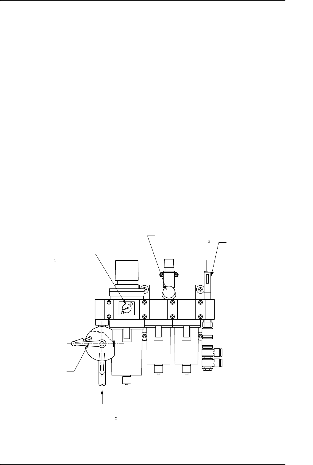
3. Confirmation and Procedure of Power Supply
(1) Confirmation of Power and Air Sources
Confirm that power and air are supplied to the machine.
• Power Source : 200 V AC, 3-Phase
• Air Source: Air Pressure : 0.49 to 0.69 MPa (dry and clean air)
(5 to 7 kgf/cm
2
)
Set Pressure : Main Pressure : 0.49 MPa (5 kgf/cm
2
)
Air Blowing Pressure: 0.015 MPa
(0.15 kgf/cm
2
)
Note: Do not change the set pressure. Otherwise, accurate placement
cannot be expected.
• Use of Dry and Clean Air
If moisture, oil, or dust enters the penumatic equipment (an air cylin-
der, etc.) of the component placement machine, it may result in a break-
down of the machine.
Moisture, oil, or dust entrained in the vacuum route will also cause an
error in the component pick-up and placement operation.
[Dry and Clean Air]
Moisture : Dew Point -17°C or lower (Atmospheric Pressure)
Oil : 0.1 mg/m
3
or less (ANR)
Dust : Solid Material 0.01 µm or less
Fig. 2.17
9910-001 2-20 Tg0246-PM-OP
3. Confirmation and Procedure of Power Supply
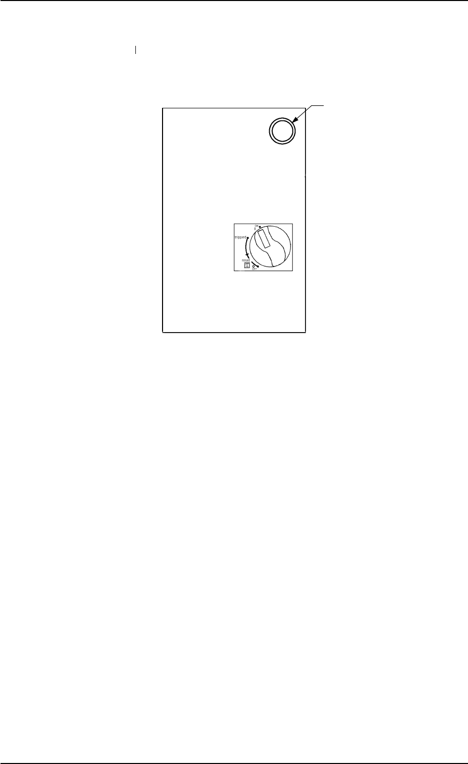
Main Power Lamp
(2) Power Breaker ON
Set the power breaker crank located at the front side of the machine to
“ON” (
).
The main power lamp illuminates.
(The lamp extinguishes when the crank is set to “OFF”.)
Fig. 2.18
9910-001 2-21 Tg0246-PM-OP