1OM-1064-002.pdf - 第182页
4. SEMI-AUTOMA TIC OPERA TION *4 *9 *12 *1 1 *8 *6 *7 *3 *2 *5 *1 *10 4. SEMI-AUT OMA TIC OPERA TION • This function enables special start-up operations such as resetting and con- tinuous starting of semi-automatic opera…

3. AUTO OPN SUB-MENU Display
Table 3.1-2
9910-001 3-12 Tg0246-PM-OP
Footnote
THE NOZZLE TYPE DATA IS TOO LARGE FOR THE AVAILABLE MEMORY SPACE.
CAN NOT SAVE DATA, BECAUSE TEACH RESULT DATA WAS ERROR.
CANNOT PERFORM OPERATION IN BEAM-B HEADS.
NOT COMPLETE SAVE FD PREVIOUS DATA.
CANNOT PERFORM OPERATION IN DRAWING PALLET.
THE VALUE OF TRAY HEIGHT IS OUT OF RANGE.
CANNOT SELECT MENU DURING P.E.C. RECOG. NOT COMPLETED.
CANNOT SELECT MENU DURING UNIT P.C.B. B.B.R. NOT COMPLETED.
CANNOT SELECT MENU DURING PATTERN OFFSET TEACH. (TEMPORARY ENTRY
MODE)
CANNOT SELECT MENU DURING PLACEMENT POSITION TEACH. (TEMPORARY
ENTRY MODE)
CANNOT SELECT MENU DURING 1POINT MODE TEACH.
CANNOT SELECT MENU DURING 1POINT TEACH STATUS. (NOT COMPLETE)
CANNOT SELECT MENU. PLACEMENT POSITION TEACH IS NOT TEMPORARY ENTRY
MODE.
PLACEMENT POSITION TEACH IS NOT SET ILLEGAL DATA.
NOT AVAILABLE PLACEMENT PATTERN PROGRAM STEP.
PLEASE RELEASE A PREPARATIONS COMPLETION OF BEAM-A.
PLEASE RELEASE A PREPARATIONS COMPLETION OF BEAM-B.
CAN NOT PERFORM OPE. BANK CRG. CART IS NOT LOC. AT CONNECT OR
DISCONNECT POS.
OPEN THE COMPONENT SUPPLY COVER [A].
OPEN THE COMPONENT SUPPLY COVER [B].
OPERATION DENIED BY THIS SCREEN.
CANNOT SELECT MENU IN [WAIT] MODE AS PLACEMENT MODE.
SET THE SAFETY BAR [A].
SET THE SAFETY BAR [B].
TURN ON THE [POWER ON] BUTTON.
CIRCUIT PROTECTOR FOR FEEDER [A] (BACK SIDE) IS ACTIVE.
CIRCUIT PROTECTOR FOR FEEDER [B] (FRONT SIDE) IS ACTIVE.
YA-AXIS LOCATE STOPPER FORWARD LIMIT NOT DETECTED.
YB-AXIS LOCATE STOPPER FORWARD LIMIT NOT DETECTED.
ZERO YA-AXIS.
ZERO YB-AXIS.
ZERO TFA1-AXIS.
ZERO TFB1-AXIS.
CANNOT SELECT MENU DURING BANK CARRIAGE CART DISCONNECT.
CAN NOT OPERATION, BECAUSE HEAD IS BYPASSED.
CAN NOT OPERATION, BECAUSE CAMERA IS BYPASSED.
CAN NOT OPERATION, BECAUSE USEFUL NOZZLE IS SHORTAGE.
CAN NOT SAVE DATA, PLEASE USE ANOTHER FD.
CAN NOT OPERATION, BECAUSE SIF CHECK MODE.
4. SEMI-AUTOMATIC OPERATION
*4*9*12*11*8
*6
*7
*3
*2
*5
*1
*10
4. SEMI-AUTOMATIC OPERATION
• This function enables special start-up operations such as resetting and con-
tinuous starting of semi-automatic operation from the P.C.B. in the middle
of process after power is turned off and starting of placement operation
from the middle of steps after system clear.
• Components can be placed on the positioned P.C.B. from the desired step
No. or only one component in the desired step No. can be placed on the
P.C.B.
4.1 Normal Step Designation (Without Non-Placement
Steps)
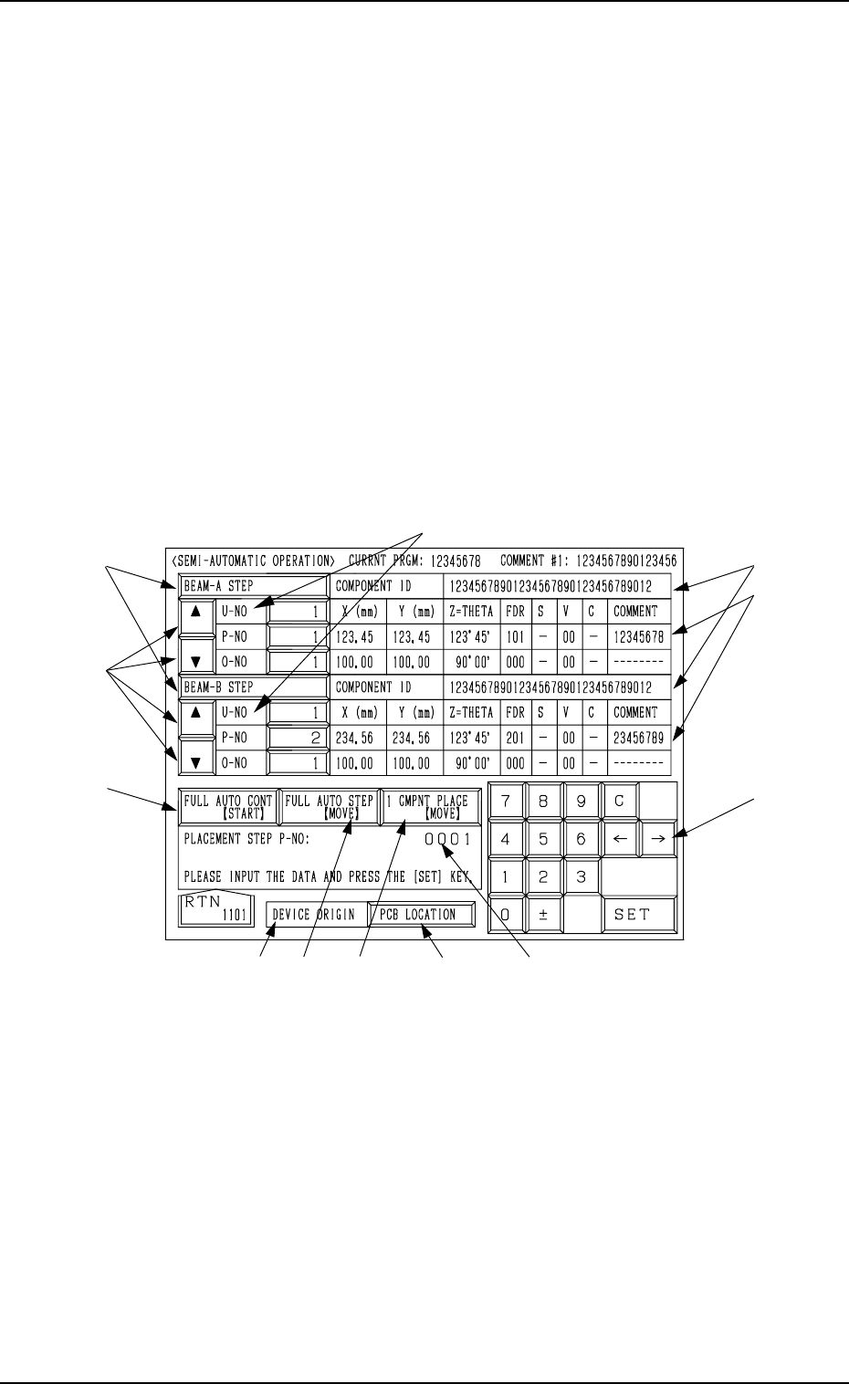
When the [SEMI-AUTOMATIC OPERATION] key is pressed at the “AUTO
OPN SUB-MENU” display, the following display appears on the screen.
Note: This key can be selected only when the machine is in the “STOP” mode.
Fig. 3.3
*1 [BEAM-A STEP] and [BEAM-B STEP] keys
Specify the beam to be operated.
When the selected key illuminates in blue, the corresponding beam can be
operated.
If not, the beam cannot be operated.
Every time the key is pressed, the key turns blue or not.
0004-002 3-13 Tg0246-PM-OP

4. SEMI-AUTOMATIC OPERATION
*2 [U-NO], [P-NO] and [O-NO] key
Step No. from which the placement operation starts
When repetitive placement data is not used (No O-No. data), “----” ap-
pears in the “O-NO” data box.
To set step No., select this key and enter a parameter using the ten-key
pad. Then, press the [SET] key.
(When the step No. in the “U-NO” data box is changed, “0001” is auto-
matically set in the “P-NO” and “O-NO” data boxes.)
Note: When a non-existing step No. is specified and the [SET] key is
pressed, an error message is issued, indicating that no data entry is
possible.
*3 Ten-Key Pad for Parameter Entry
*4 Entered Parameter Display Section
When the [SET] key is pressed, the displayed parameter is specified as
operation start step *2.
*5 [ ] and [ ] key
These keys are used to change the step No. from which the placement
operation starts.
To change the step No., select the step No. data box *2 and press the [ ]
or the [ ] key. The step No. scrolls up or down one by one.
When the [ ] key is pressed, the step No. increases. Pressing the [ ] key
decreases the step No.
*6 Component IDs used in the specified steps
Component IDs used in the steps as operation start ones are displayed.
*7 Comments of the step Nos. specified as operation start steps are displayed.
*8 DEVICE ORIGIN
Origin Monitor Section
When the devices are located at their origins, this label turns green.
When they are not at their origins, it turns light red.
Note: Semi-automatic operation cannot be performed when the devices
are not at their origins.
*9 [P.C.B. LOCATION] key
This display section indicates how the P.C.B. is positioned.
When a P.C.B. is correctly positioned, this key turns green.
When there is no P.C.B. or a P.C.B. is not positioned correctly, it turns
light red.
Note: When a P.C.B. is not positioned correctly, the semi-automatic op-
eration cannot be performed.
When the [P.C.B. LOCATION] key is pressed, the “MANUAL TRANS-
FER OPERATION” display appears on the screen.
Refer to “8. Manual Transfer Operation of Section 4” for details.
When *8 and *9 are green, it indicates that the semi-automatic operation
is set ready.
9910-001 3-14 Tg0246-PM-OP