1OM-1064-002.pdf - 第57页
3.17 Simultaneous Recognition Function When the right and left heads pick up components and move to the component recognition camera positions through the simultaneous pick-up and pick-up pri- ority functions and the pic…

3.14 HDD/FDD Functions
The machine is provided with an FDD on the front console panel (front side of
machine) and the machine data can be loaded from or saved in a floppy disk
(3.5'' floppy disk).
HDD : Hard Disk Drive
FDD : Floppy Disk Drive
• The pattern program can be saved from the main machine side (hard disk) to
a floppy disk.
A file of data is created in the same format as the programming device (op-
tion) and the created file can be loaded to the programming device.
• The pattern program stored in a floppy disk can be loaded to the main ma-
chine.
The pattern program created by the programming device (option) can be
loaded to the machine. (The component library data can not be leaded.)
• The pattern program in a floppy disk can be deleted.
• All backup data can be saved from the main machine side to floppy disks.
It is recommended that all backup data should be saved in floppy disks be-
cause it can be used for data analysis after error occurrence.
Note: Special operation is required when all backup data must be loaded.
Refer to “10. HDD
FDD Functions of Section 3 in Volume 4” for details.
3.15 Simultaneous Pick-Up Function
This function makes it possible for the right and left heads to descend at the
same time and pick up components from the tape feeders installed at an interval
equal to the pitch (design value: 108 mm) of both heads. The cycle time can be
shortened by this function. (Set “1” in the “S” data field of the placement data.)
Refer to “2.6.2 PLACEMENT DATA (P) Display [Component Placement
Data] of Section 2 in Volume 2” for details.
3.16 Pick-Up Priority Function
This function is based on the idea that the beams can be operated efficiently if
two heads (right and left heads) can pick up components at the same time and
follow the component placement sequence.
By pairing two steps of placement data (setting “2” in the “S” data field of the
placement data), each component can automatically be placed efficiently in the
order of the specified placement steps through the sequence “Pick → Pick →
Recognition → Recognition → Place → Place”.
The automatic feeder axis adjustment mode becomes valid for both right and
left heads when components are picked up.
Refer to “2.6.2 PLACEMENT DATA (P) Display [Component Placement
Data] of Section 2 in Volume 2” for details.
3. Functions
0103-002 1-26 Tg0246-PM-OP

3.17 Simultaneous Recognition Function
When the right and left heads pick up components and move to the component
recognition camera positions through the simultaneous pick-up and pick-up pri-
ority functions and the picked components and the visual fields of the two con-
fronting component recognition cameras are combined in conformity with each
other, this function can be activated to capture the images of the components for
simultaneous component recognition.
Refer to “16. HEAD OFFSET (GET BOTH IMAGE) Display of Section 5 in
Volume 2” and “6.6 HEAD OFFSET (GET BOTH IMAGE) Display of Sec-
tion 3 in Volume 4” for details.
0103-002 1-27 Tg0246-PM-OP
3. Functions
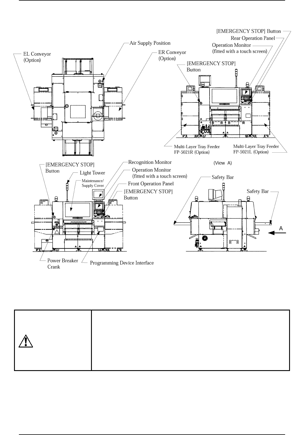
4. Structure and Names
WARNING
Press one of the [EMERGENCY STOP] buttons
to stop the machine immediately in an emergency.
The power is turned off and the machine stops
running immediately.
4. Structure and Names
Fig. 1.5
0308-004 1-28
Tg0246-PM-OP