1OM-1064-002.pdf - 第142页
5. Preparation and Confirmation before Operation A B [T ape Feeders] Fig. 2.27 [Vibratory Stick Feeders] Fig. 2.28 [T ray Feeders] (Option) Fig. 2.29 C 0004-002 2-44 Tg0246-PM-OP
5. Preparation and Confirmation before Operation
9910-001 2-43 Tg0246-PM-OP
5.2.5 Feeder (B) Offset
The feeder (B) offset data contains the offset data to correct the positional
deviation in component pick-up positions caused due to the variation in tape
feeders.
The offset data is automatically updated through component recognition pro-
cessing during automatic operation (the recognition performed to track the
positional relation between the vacuum nozzle and component centers) such
that components can be picked up at their centers.
Notes: (a) The offset data is updated automatically only when “ENABLE”
is set in the “AUTOMATIC FEEDER AXIS SETTING” data
boxes at the “AUTOMATIC FEEDER AXIS ADJUSTMENT
MODE” display.
To change the data manually, press the related key and enter a
parameter using the ten-key pad. When the [SET] key is pressed,
the entered data is set.
(b) The offset data gives some effect on the pick-up rate, etc. In nor-
mal cases, do not change or delete it unless necessary. Use each
display only to check the parameters.
(c) When some feeders are replaced for a program change, etc., clear
the parameters (the parameters corresponding to the feeder slot
Nos. (FDR NO.) where the replaced feeders are installed) to "0"
(zero).
Clear the parameters in each step to “0” (zero) for the tray feeders
(option).
When the previous value (the value before change) is large, a
component pick-up error will occur.
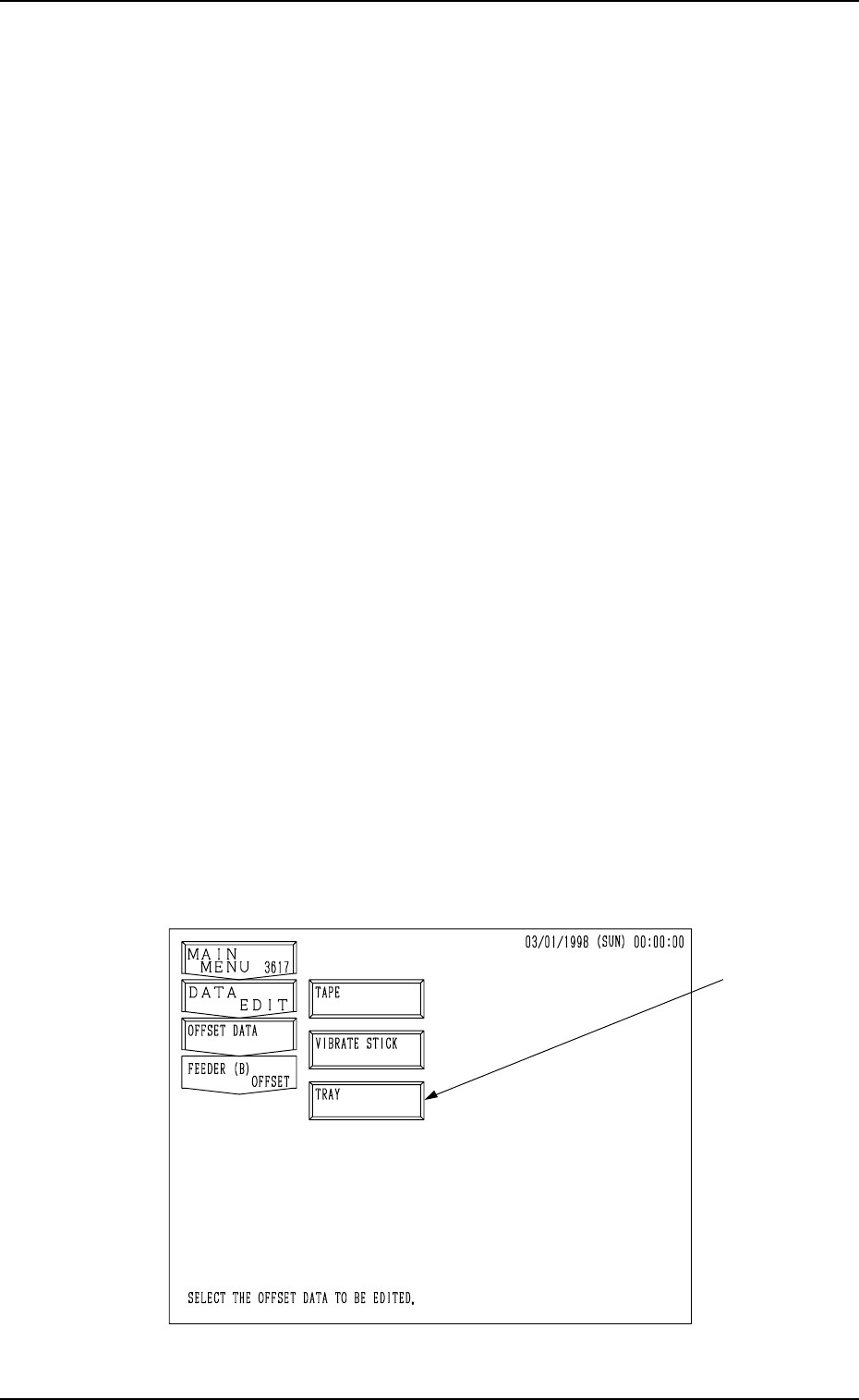
When the [FEEER (B) OFFSET] key is pressed at the “RECOVERY OPN.
TEACHING OPN.” display, the following display appears on the screen. (Hi-
erarchical Sequence: “AUTO OPN MODE (PLACEMENT)” Display →
“AUTO OPN SUB-MENU” Display → “RECOVERY OPN. TEACHING
OPN.” Display)
Note: The -marked function is optional.
Fig. 2.26
5. Preparation and Confirmation before Operation
A
B
[Tape Feeders]
Fig. 2.27
[Vibratory Stick Feeders]
Fig. 2.28
[Tray Feeders] (Option)
Fig. 2.29
C
0004-002 2-44 Tg0246-PM-OP
5. Preparation and Confirmation before Operation
E
F
G
D
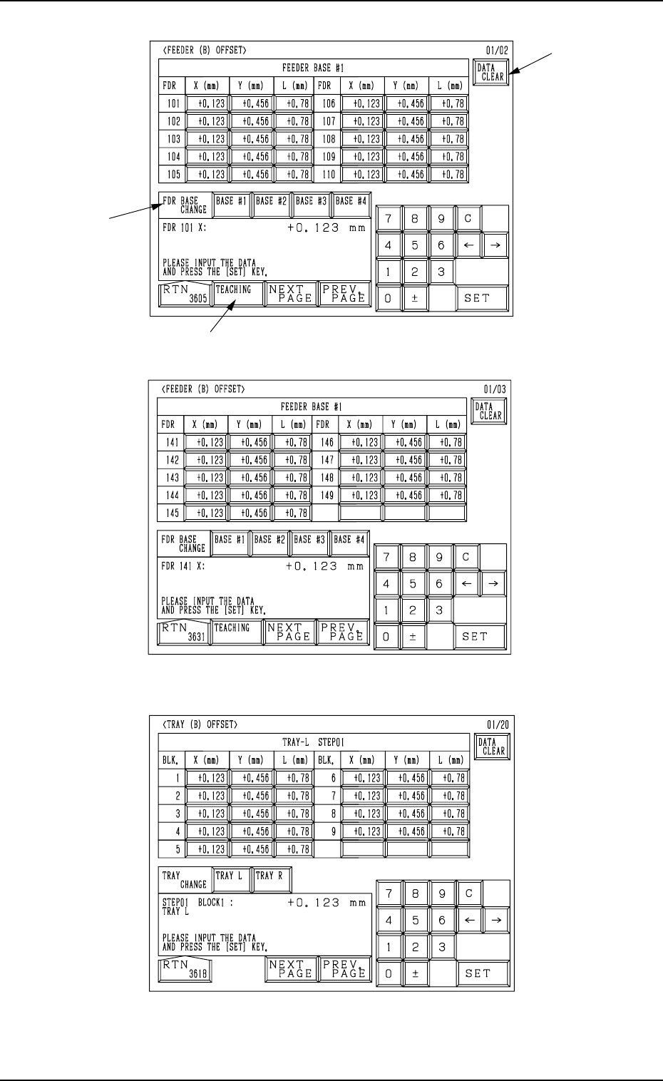
Operation Procedure
(1) Select the line of offset parameters to be changed or deleted by pressing
the corresponding “FDR.” key at the “FEEDER (B) OFFSET” display
(Fig. 2.27, 2.28, or 2.29).
Part of the display layout differs depending on the selected type of feed-
ers.
(2) Select how to change or clear the offset data.
• To change or clear the offset data individually
*1 Select the required key.
*2 Enter a parameter and press the [SET] key. The entered parameter is
defined.
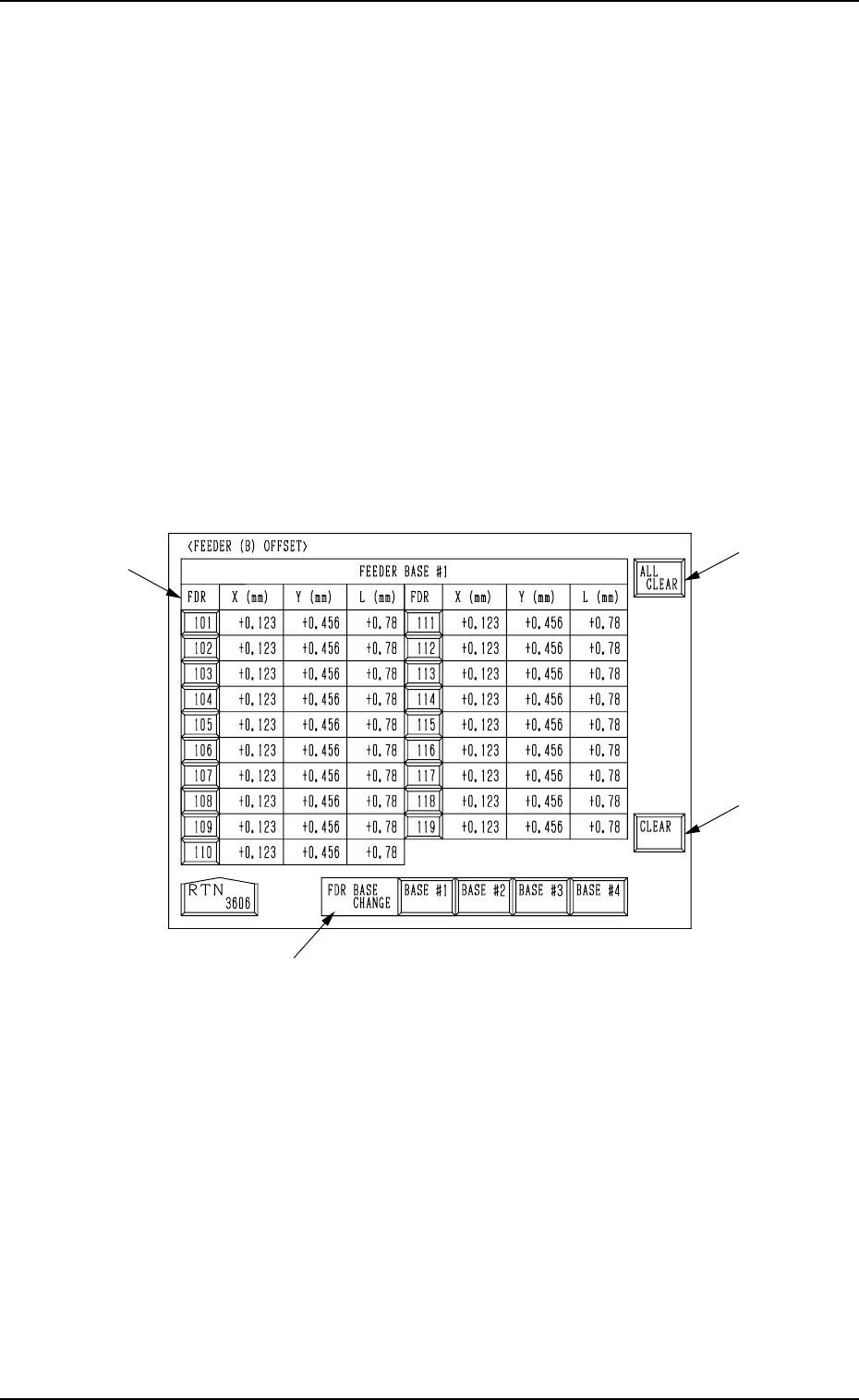
• To clear the offset data individually (for each individual feeders) or all
the offset data at a time, proceed to Step (3).
(3) Press the [DATA CLEAR] key A at the “FEEDER (B) OFFSET” display.
Another “FEEDER (B) OFFSET” display appears on the screen, enabling
you to clear the offset data.
0004-002 2-45 Tg0246-PM-OP
Fig. 2.30