1OM-1064-002.pdf - 第103页
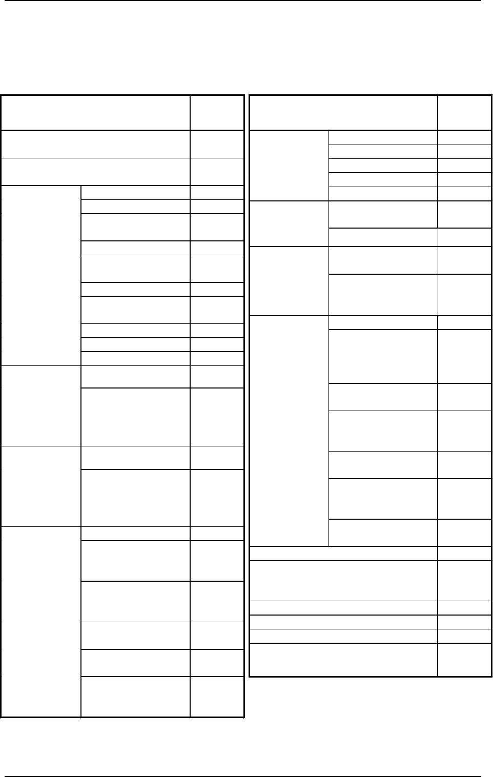
1. Notes Oper ati on I tem s O p er at i on Po ssib le / Impossible X Axis × Y Axis × Up / D own S h a ft × H ead R otatio n al Shaf t × Man u al Axi s Ope r atio n Bac kup U p/Dow n Sh aft { Movem en t t o T a r g et Po…
1. Notes
WARNING
1. Do not keep the selection key inserted unless necessary. The key
shall be stored by the person in charge.
2. Only the trained personnel shall operate the machine when the [OP-
ERATION/SET UP] switch is set to the “SET UP” side. Otherwise, it
may cause critical injury to the operator.
3. When the [OPERATION/SET UP] switch is set to the “SET UP” side,
the operator can operate the machine with the maintenance cover
open.
It is very dangerous to operate the machine without safety check. Be
sure to pay a special caution while operating the machine.
The [OPERATION/SET UP] switch must be kept in the “OPERATION”
side in normal cases to avoid any danger.
1.2 [OPERATION/SET UP] Switch
When the [OPERATION/SET UP] switch is set to the “SET UP” side, the
interlock functions of the maintenance/supply cover and the safety bar are
partly canceled, making it possible to perform set-up operations with the main-
tenance cover opened (limited to the actions taken without any X/Y beam move-
ment).
0004-002 2-4 Tg0246-PM-OP
• The [OPERATION/SET UP] switch becomes effective only when the fol-
lowing requirements are fulfilled.
(1) The machine must be set in the “STOP” mode.
(2) Operations must be performed on the operation available side.
(3) The maintenance/supply cover and the safety bar on the operation un-
available side must be closed.
(4) The up/down axis (LA1, LA2, LB1, and LB2 axis) on each beam must
be located at their origins (NEAR).
• The selection key must be used to change over the [OPERATION/SET UP]
switch.
• When the [OPERATION/SET UP] switch is set to the “SET UP” side, all
tower lights (red, yellow, and green) illuminate.
• When the [OPERATION/SET UP] switch is set to the “SET UP” side, the
power to drive the X/Y beam is shut off.
1. Notes
Operation Items
Operation
Possible/
Impossible
X Axis
×
Y Axis
×
Up/Down Shaft
×
Head Rotational Shaft
×
Manual Axis
Operation
Backup Up/Down Shaft
{
Movement to Target
Position
{
Set-Up
(Conveyor
Width)
Manual Axis Operation
{
Air Supply
(Beams A and B)
{
Manual
Subsystem
Operation
Pick-Up/Blowing
(LA1 and LA2 Axis,
LB1 and LB2 Axis)
{
P.C.B. Transfer
{
Backup Base
Movement
(Positioning, Standby,
and Origin Positions)
{
P.C.B. Locating Side
Clamp
{
L/P/R Conveyors
(Normal/Reverse
Rotation)
{
P/R Conveyor P.C.B.
Stopper
{
EL/ER Conveyors
(Normal/Reverse
Rotation)
{
Manual
Transfer
Operation
EL/ER Conveyer
P.C.B. Stopper
{
Teaching
×
Recognition Test
(P.C.B. and Component Recognition
Functions)
×
Automatic Operation
×
System Clear
×
ET Communication (RS-232C)
×
Tray Feeder (“Feeder Change-Over
Preparation Complete” Operation)
{
Operation Items
Operation
Possible/
Impossible
Operation on Available Operation Panel
Side
{
Operation on Unavailable Operation Panel
Side
×
Zeroing Operation
×
Backup Up/Down Shaft
{
Conveyor Width
Variable Shaft
{
Tray L and R
{
All Beams and Beams
A and B
×
X/Y Shaft
×
Head (Up/Down and
Rotational Shafts)
×
Up/Down Shaft
×
Head Rotational Shaft
×
Zeroing
Feeder Base
{
Traverse Shaft
{
Tray Feeder
Manual
Subsystem
Operation
(Zeroing
Operation)
Elevator Shaft
{
Traverse Shaft
{
Tray Feeder
Manual
Subsystem
Operation
(Manual
Operation)
Elevator Shaft
{
Tape Feed
{
L/P/R Conveyors
(Normal/Reverse
Rotation)
{
EL/ER Conveyors
(Normal/Reverse
Rotation)
{
Servomotor Adjustment
(X, Y)
×
Servomotor Adjustment
(L)
×
Unit Adjustment
Servomotor Adjustment
(Backup Up/Down
Shaft)
{
Case: The [OPERATION/SET UP] switch is set to the “SET UP”
side.
{ : Operation Possible
× : Operation Impossible
9910-001 2-5 Tg0246-PM-OP
1. Notes
1.3 Touch Screen
• Since the touch screen uses the molecules in liquid crystals, do not apply
strong pressure to the touch screen.
Try not to touch the screen except for input operations.
The touch screen reacts to the force of 0.78N (80g) or less.
Do not press the screen with an excessive force.
CAUTION
The surface of the touch screen is fragile. Do
not rub the surface nor touch it with a pen, a
screwdriver, etc.
CAUTION
The machine is not a water-proof and encap-
sulated type.
Avoid dust, water droplet, oil droplet, metal
pieces.
Especially, when metal pieces or combustible
material are mixed into the machine, it may lead
to fire ignition.
• When power is supplied to the machine at low temperature, the brightness
of the back light deteriorates but resumes normal in a few minutes.
The deterioration is not abnormal.
When the back light is turned on or off repeatedly at low temperature, the
life will be shortened.
• Caution before Touch Screen Cleaning
CAUTION
Turn off the operation power before the touch
screen is cleaned.
Cleaning the screen while it is active may cause
adverse reaction of the screen, resulting in data
corruption.
When the surface of the touch screen is stained, wipe off dust and dirt with a
dry cloth.
Do not use alcohol, benzene, etc.
CAUTION
Do not use alcohol or benzene to clean the
touch screen.
Otherwise, the surface of the touch screen may
melt or get cloudy.
• To Correct the Drift of the Touch Screen Sensors
The touch screen sensors should be adjusted to compensate for the drift
between the reacting part of the touch screen sensors and the screen images.
Refer to “Section 5 Touch Screen in Volume 4” for the adjustment.
0004-002 2-6 Tg0246-PM-OP