1OM-1064-002.pdf - 第221页
3. Program Change 3. Program Change When the [PROGRAM CHANGE] key is pressed at the “MANUAL MODE” display , the following display appears on the screen. This display can also be opened from the “P A TTERN PROGRAM” displa…

9910-001 4-4 Tg0246-PM-OP
2. MANUAL MODE Display
*6 When this key is pressed, the “MANUAL TRANSFER OPERATION” dis-
play appears on the screen, enabling the manual P.C.B. input and output
operations and the cycle operation of each individual conveyors and P.C.B.
stoppers.
Note: This display can be opened only when the machine is in the “STOP”
mode.
*7 When this key is pressed, the “MANUAL NOZZLE CHANGE OPERA-
TION” display appears on the screen, enabling the cycle operation for open-
ing or closing the nozzle stocker and attaching or storing a vacuum nozzle
through manual operations.
*8 When this key is pressed, the “PCB SUPPORT PINS SET-UP MODE”
display appears on the screen, enabling the setting of the environmental
condition required to specify the position of the P.C.B. support pins.
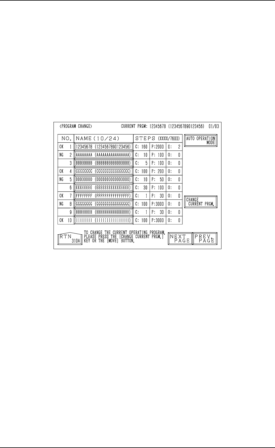
3. Program Change
3. Program Change
When the [PROGRAM CHANGE] key is pressed at the “MANUAL MODE”
display, the following display appears on the screen.
This display can also be opened from the “PATTERN PROGRAM”
display. (Hierarchical Sequence: “AUTO OPN MODE (PLACE-
MENT)” Display → “AUTO OPN. SUB-MENU” display → “PATTERN
PROGRAM” Display)
Note: This key can be selected only when the machine is in the “STOP”
mode.
Fig. 4.2
Refer to “5.2.1 Selection of Current Pattern Program (Program Change) of
Section 2” for details.
9910-001 4-5 Tg0246-PM-OP
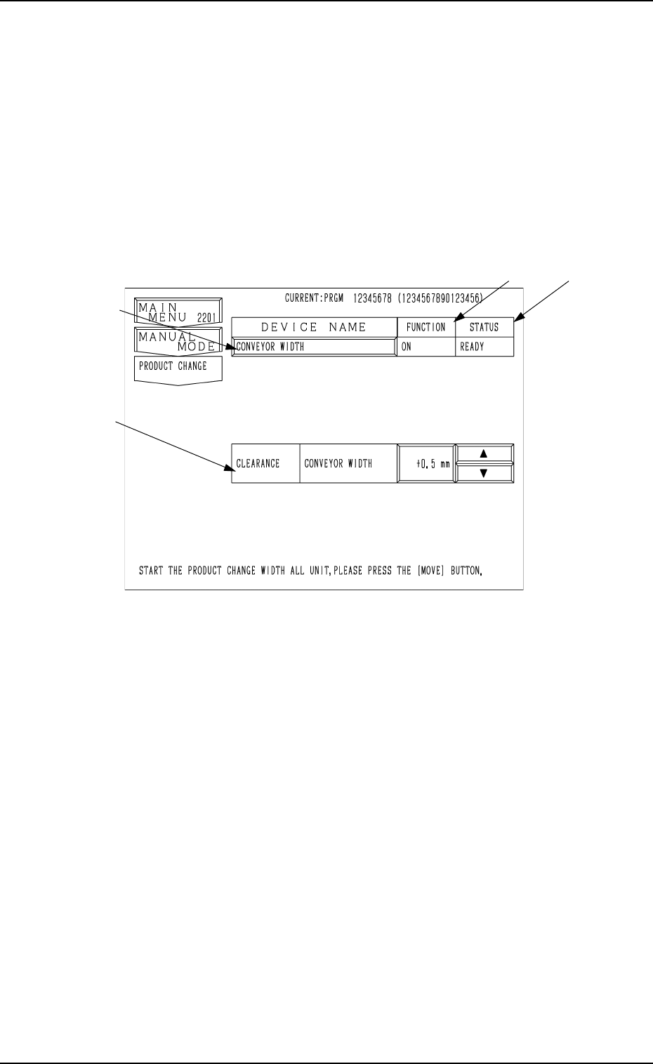
4. Product Change
4.1 Selection of Set-Up Menus and Overall Set-Up Op-
eration
When the [PRODUCT CHANGE] key is pressed at the “MANUAL MODE”
display, the following display appears on the screen.
When the [PRODUCT CHANGE] key is pressed at the “AUTO OPN.
SUB-MENU” display, the same display appears on the screen.
*4
*3
*1
*2
9910-001 4-6 Tg0246-PM-OP
4. Product Change
Fig. 4.3
• When this display is active and the [MOVE] button is pressed, the machine
automatically sets up all the devices for which “ON” is set in the “MODE”
data boxes at the “SET-UP DATA” display. (Hierarchical Sequence: “DATA
EDIT” Display → “PATTERN PROGRAM” Display → “SET-UP DATA”
Display)
Note: When the [OPERATION/SET UP] switch is set to the “SET UP”
side, the set-up operation cannot be performed.
Ref.: Before the conveyor width set-up operation is initiated, each con-
veyor is automatically activated to check that no P.C.B. is located at
any irregular position.
*1 [CONVEYOR WIDTH] Key
When this key is pressed, the “CONVEYOR WIDTH” display appears on
the screen, enabling the manual set-up operation of each individual de-
vices.
*2 FUNCTION (“ON” or “OFF”)
Shown in the text box is the parameter set at the “SET-UP DATA” display.
(Hierarchical Sequence: “PATTERN PROGRAM” Display → “SET-UP
DATA” Display)