1OM-1064-002.pdf - 第97页
8. V acuum Nozzles 9910-001 1-67 Tg0246-PM-OP T able 1.12- 1 Notes: ( a ) A handling test may be required depending on the shape, etc., of the components in the column entitled “Component Size”. (b) The dimensions of the…
8. Vacuum Nozzles
8. Vacuum Nozzles
List of Nozzle Types
The machine is equipped with vacuum nozzles designated in the delivery speci-
fications at shipment.
Unit: mm
Table 1.1
2
9910-001 1-66 Tg0246-PM-OP
Code
Nozzle Type
(a)
Component Size
(Referential Values)
(
mm
)
(
b
)
Applicable Components
(For Reference)
Part No.
Part Name
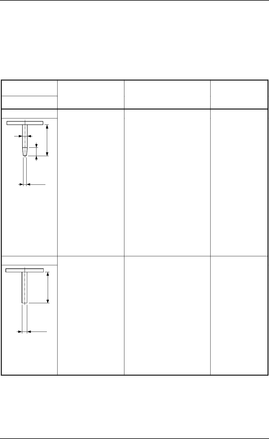
MA04
19
3
4.5
Inside Diameter
φ
1.1
Outside Diameter
φ
1.8
2.5
×
2.0 to 4.0
×
4.0
Capacitors and Resistors of 3225
to 6432 Types
Network Resistors of 2520 Type
Inductors of 4525 Type
Horn Tantalum Capacitors of
3427 to 4527 Types
Tantalum Electrolytic Capacitors
A, B, and B2
Ferrite Chip Beads of 3216 to
4532 Types
LEDs (2924 to 3427)
Transistors (4525)
Diodes of 4525 to 4738 Types
Aluminum Electrolytic Capacitors
(φ3)
Coils (2.5 × 2.5 to 4 × 4)
Filters (4532)
Oscillators (7.2 × 2.8 × 2.5)
Trimmer Capacitors
Semi-Fixed Variable Resistors
Other similar-shaped components
630 075 9044
NOZZLE (MA04)
MA05
19
Inside Diameter
φ
2.0
Outside Diameter
φ
3.0
4.0
×
4.0 to 12.5
×
5.5
Capacitors and Resistors of 4532
to 5780 Types
Inductors of 5650 Types
Horn Tantalum Capacitors of
5644 to 5646 Types
Tantalum Electrolytic Capacitors
B, C, D, G, N
Aluminum Electrolytic Capacitors
(φ4, φ5)
Coils (4 × 4 to 6 × 6)
Filters, Single, Double, Triple
Oscillators (7.3 × 5.0 × 2.6)
Trimmer Capacitors
Semi-Fixed Variable Resistors
Switches
SOP, SOJ 8 to 16 Pins
Other similar-shaped components
630 075 9051
NOZZLE (MA05)
8. Vacuum Nozzles
9910-001 1-67 Tg0246-PM-OP
Table 1.12-1
Notes: (a) A handling test may be required depending on the shape, etc., of
the components in the column entitled “Component Size”.
(b) The dimensions of the components entitled “Applicable Compo-
nents for Reference” differ depending on the component mak-
ers. The dimensions are shown only for your reference.
(c) Consult our sales personnel for details of nozzles other than those
listed in the tables.
(d) There is a possibility that the component and the structure inter-
fere with each other when the vacuum nozzle not suitable for the
component shape is used.
Be sure to use the vacuum nozzle suitable for the component
shape.
Code
Nozzle Type
(a)
Component Size
(Referential Values)
(
mm
)
(
b
)
Applicable Components
(For Reference)
Part No.
Part Name
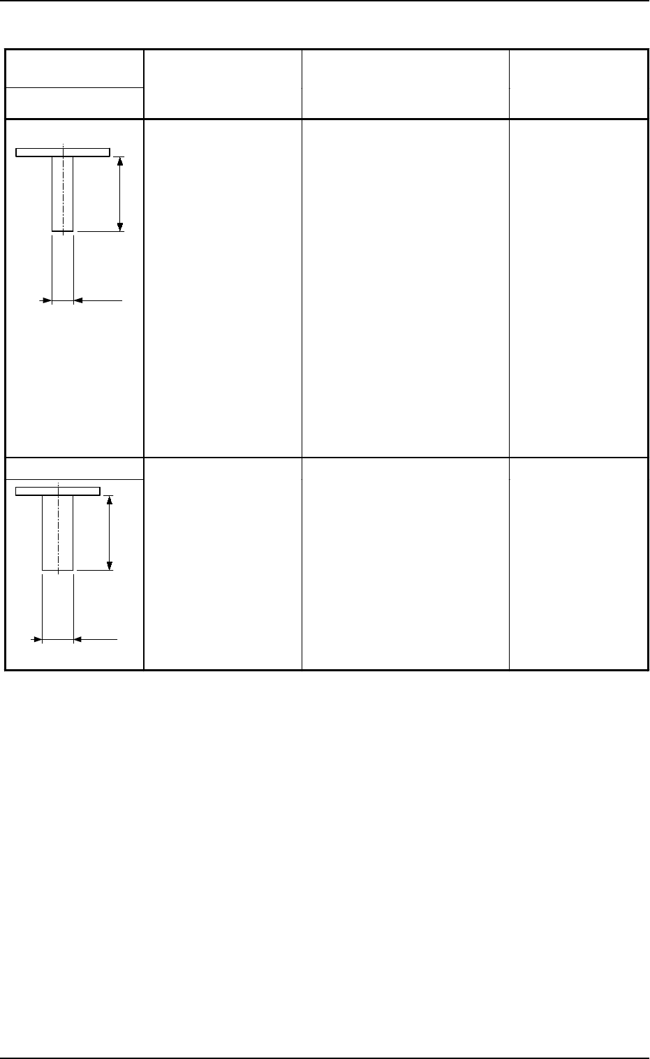
MA06
19
Inside Diameter
φ
3.0
Outside Diameter
φ
5.0
6
×
6 to 16
×
12.5
Capacitors and Resistors of 7563
to 10 ×
8 Types
Varistors (8 × 6.3 to 16 × 12.5)
Transistors (6550)
Aluminum Electrolytic Capacitors
(φ6, φ8, φ10)
Coils (6 × 6 to 11 × 11)
Filters, Single, Double, Triple
Oscillators (10 × 8 × 3.8)
Trimmer Capacitors
Rotary Switches
DIP Switches
SOP, SOJ 18 Pins or More
QFP (smaller than 14 × 14)
PLCC (smaller than 14 × 14)
Other similar-shaped components
630 075 9068
NOZZLE (MA06)
MF01
19
Inside Diameter
φ
3.0
Outside Diameter
φ
8.0
11
×
11 to 20
×
20
Coils (larger than 11 × 11)
QFP (14 × 14 to 20 × 20)
PLCC (14 × 14 to 20 × 20)
Other similar-shaped components
630 075 9075
NOZZLE (MF01)
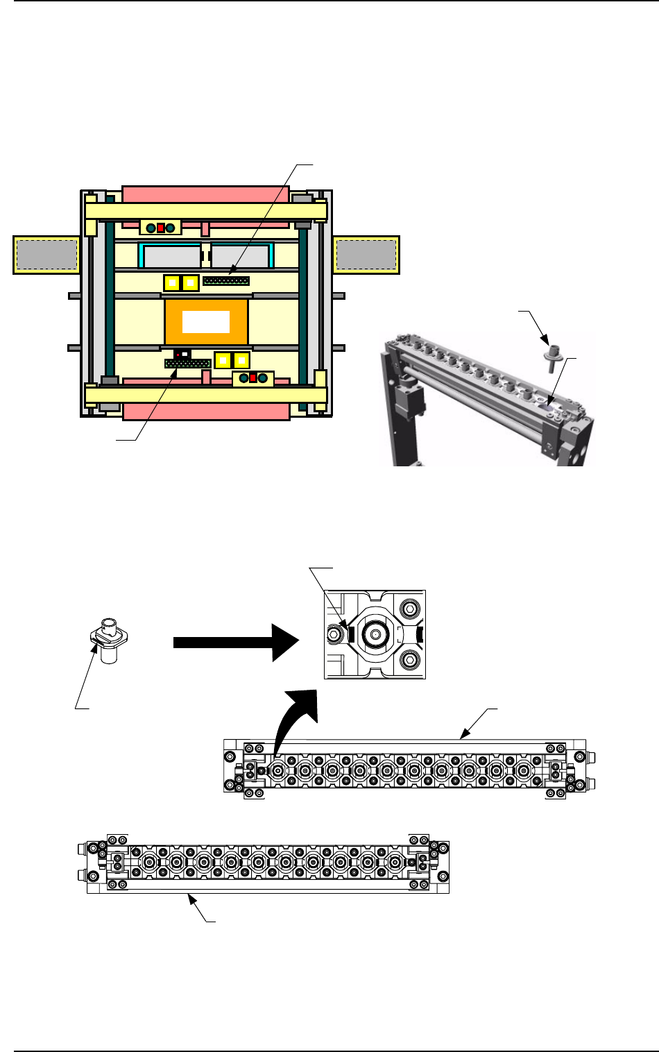
Nozzle Stocker
Set the nozzles in the nozzle storage section of the nozzle stocker.
The nozzles must be set as shown in Fig. 1.32-3.
Direct the imprinted nozzle ID mark as shown in the figure and insert the nozzle
into the groove.
Beam A Side
Beam B Side
Front Side of Machine
Fig. 1.32-1 Nozzle Stocker Position Fig. 1.32-2 Rough View of Nozzle Stocker
Fig. 1.32-3 Direction of Nozzle Arrangement
Nozzle
Storage Section
Nozzle Stocker B
Nozzle Stocker A
Set the nozzle in the nozzle stocker,
taking care of the direction of the
nozzle.
Imprinted Nozzle ID
Nozzle Stocker A
Nozzle
Imprinted Nozzle ID
Nozzle Stocker
B
Beam B Side
Front Side of Machine
8. Vacuum Nozzles
0103-002 1-68 Tg0246-PM-OP
Magnified View