1OM-1064-002.pdf - 第49页
40. Requirements for Simultaneous Component Picks (1) Feeders A vailable for Simultaneous Component Picks T ape Feeders (2) Requirements for Simultaneous Picks As the distance between the nozzle rotational centers of Hea…

2. Specifications
9910-001 1-18 Tg0246-PM-OP
(2) Stick Components
Note: Some components cannot be used due to the mechanical char-
acteristics and shapes, etc. Consult our sales personnel for
details.
(3) Tray Components
Notes: (a) In the case of the connector, this recognition can be
applied to Max. 150
× 26 mm.
(b) Irregular-shaped components can also be used when an
optional device is provided.
(c) Some components cannot be used due to the mechani-
cal characteristics and shapes, etc. Consult our sales
personnel for details.
Packaging Standard
Applicable Components for Reference
t
a
d
b
c
abcd t
Lead End
Thickness
Mass
Min.
7755 − 0.10 −
Max
5 5 5 5 25.4 − 20 g
•
Flat Packaged ICs
•
Connector
•
Other similar-shaped components
Packaging Standard
Applicable Components for Reference
t
a
b
Direction of
Component Feed
ab t
Min. 551
Max. 55 30 12.7
• Mini-Flat Packaged ICs (SOP-IC)
8 to 10Pins
14 to 28Pins
• PLCC
• LCC
• Other similar-shaped components
Unit : mm
40. Requirements for Simultaneous Component Picks
(1) Feeders Available for Simultaneous Component Picks
Tape Feeders
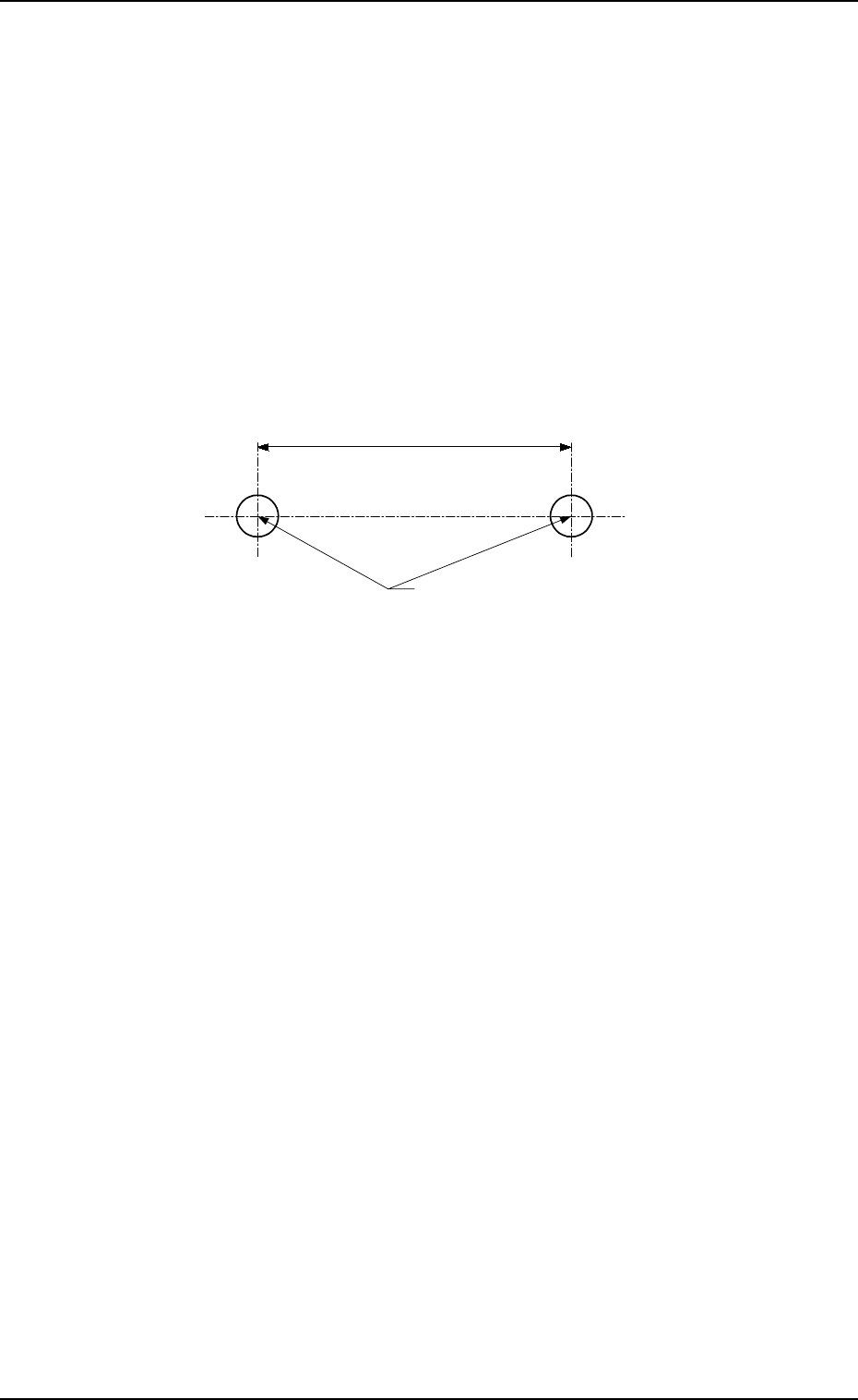
(2) Requirements for Simultaneous Picks
As the distance between the nozzle rotational centers of Heads
#1 and #2 is “108 mm”, components can be picked up simulta-
neously only when the distance of the component supply posi-
tion is “108 mm”.
Consult our sales personnel for details.
Notes: (a) When two components are on different feeder
bases, they cannot be picked up simultaneously.
(b) When a component is specified for eccentric pick-
up operation, it cannot be picked up simultaneously.
Simultaneous Pick Position
(Component Loading Position)
108
9910-001 1-19 Tg0246-PM-OP
2. Specifications
Unit : mm

41. Standard Accessory Parts List
2. Specifications
0004-002 1-20 Tg0246-PM-OP
No. Name Part No. Part Name Q'ty Remarks
1 Master Jig 630 040 4715 ASSY, FRAME 1 • For Confirmation of
Component Pick-Up
Position and Level, etc
2 PCB Backup Pin 630 075 8481 PIN, LOCATE 20 • For PCB Supporting
3-1 Vacuum Nozzle
(MA04)
630 075 9334 ASSY, NOZZLE 2 • For Component Pick
3-2 Vacuum Nozzle
(MA05)
630 075 9341 ASSY, NOZZLE 2 • For Component Pick
3-3 Vacuum Nozzle
(MA06)
630 075 9358 ASSY, NOZZLE 2 • For Component Pick
3-4 Vacuum Nozzle
(MF01)
630 075 9365 ASSY, NOZZLE 2 • For Component Pick
4 Vacuum Filter 630 069 5816 AIR LINE EQPT 80 • Spare for Dust
Removal
5 Jig for Component
Recognition Offset
630 073 0036 PLATE 1 • For Offset Teaching
(JG-0085)
6 Vacuum Filter
Replacement Jig
630 076 6691 TOOL, HAND 1 • For Vacuum Filter
Replacement
7 Empty Tape Box 630 075 2120 BOX 2 • For Empty Tape
Collection
8-1 Padlock 630 054 9676 MECH PARTS
No. 2500 30 MM
1 • To lock the power
breaker
8-2 Padlock 630 053 4917 MECH PARTS
No. 2500 25 MM
1 • To lock the main
valve of the air source
9-1 Lamp 630 000 1983 LAMP 30V 10W 2 • Spare for Light Tower
9-2 Lamp 630 075 3325 LAMP 24V 10W 2 • Spare for Component
Shortage Indicator
9-3 Lamp 630 005 5580 LAMP 2 • Spare for P.E.C.
Recognition Lighting
10-1 Fuse 423 025 2000 FUSE 250V 0.4A 2 • Spare for F201, F202,
F203, and K99
10-2 Fuse 423 022 8203 FUSE 250V 3.15A 2 • Spare for F100, F101,
F113,and F030
10-3 Fuse 423 025 1904 FUSE 250V 1.6A 2 • Spare for F102
10-4 Fuse 423 022 8005 FUSE 250V 1A 2 • Spare for F105 to F110,
F121 to F125, F152A,
F152B, F153A, F153B,
and F351A
10-5 Fuse 423 022 8104 FUSE 250V 2A 2 • Spare for F111 and
F112
10-6 Fuse 423 025 5100 FUSE 250V 4A 2 • Spare for F011 and
F021
10-7 Fuse 423 022 8302 FUSE 250V 5A 2 • Spare for F114,
F131 to F133,
F151, F161, F001,
F006, F012, and F022
10-8 Fuse 423 025 2109 FUSE 250V 6.3A 2 • Spare for F002 to
F005
10-9 Fuse 423 027 3500 FUSE 250V 0.315A 2 • Spare for F051A and
F051B
10-10 Fuse 423 022 8500 FUSE 250V 10A 2 • Spare for Recognition
Lighting Control
Board