1OM-1064-002.pdf - 第94页
7. Construction of Feeder Carriages Example: Fig. 1.30 shows how tape feeders are installed on the feeder bases. • FDR No. *01 The tape feeder cannot be installed on the feeder base because the tape interferes with the t…
7. Construction of Feeder Carriages
0308-003 1-63 Tg0246-PM-OP
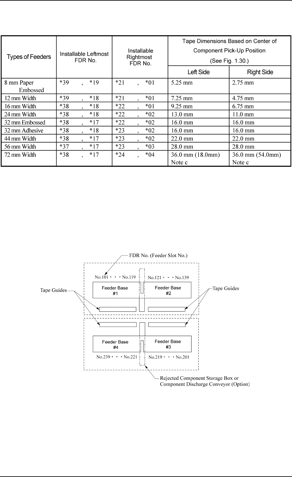
(2) Installable Feeder Slot Nos. at Both Feeder Base Ends
Note (a) Fig. 1.29 shows how the feeder bases are provided.
(b) Rejected component storage boxes or component discharge conveyors (op-
tion) can be mounted between Feeder Bases #1 and #2 and between Feeder
Bases #4 and #3.
(c) The dimensions in ( ) are those (tape width) based on the tape feeder instal-
lation position.
Table 1.10
Beam A Side
Beam B Side
(Front Side of Machine)
Fig. 1.29
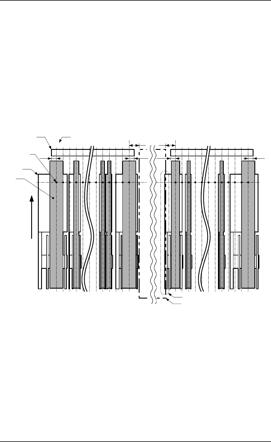
7. Construction of Feeder Carriages
Example: Fig. 1.30 shows how tape feeders are installed on the feeder bases.
• FDR No. *01
The tape feeder cannot be installed on the feeder base because the tape
interferes with the tape guide when the tape is fed out.
• FDR No. *19
The tape feeder cannot be installed on the feeder base because it inter-
feres with the rejected component storage box or the component dis-
charge conveyor (option).
• FDR No. *21
The tape feeder cannot be installed on the feeder base because the tape
interferes with the tape guide when the tape is fed out.
• FDR No. *39
The tape feeder cannot be installed on the feeder base because the tape
interferes with the tape guide when the tape is fed out.
7.3
*39
Tape Feeder
Center of Component
Pick-Up Position
Rejected Component Storage Box or
Component Discharge Conveyor (Option)
7.3
*21
*23*25*37 *35 *01*03*05
*19
*17 *15
FDR No. (Feeder Slot No.)
Tape
Tape Guide
10 10
Left Side
7.37.3
User Direction of
Tape Feed
(Direction of
Unreeling the Tape)
Right Side
Interference (Installation Impossible
)
Fig. 1.30
9910-001 1-64 Tg0246-PM-OP
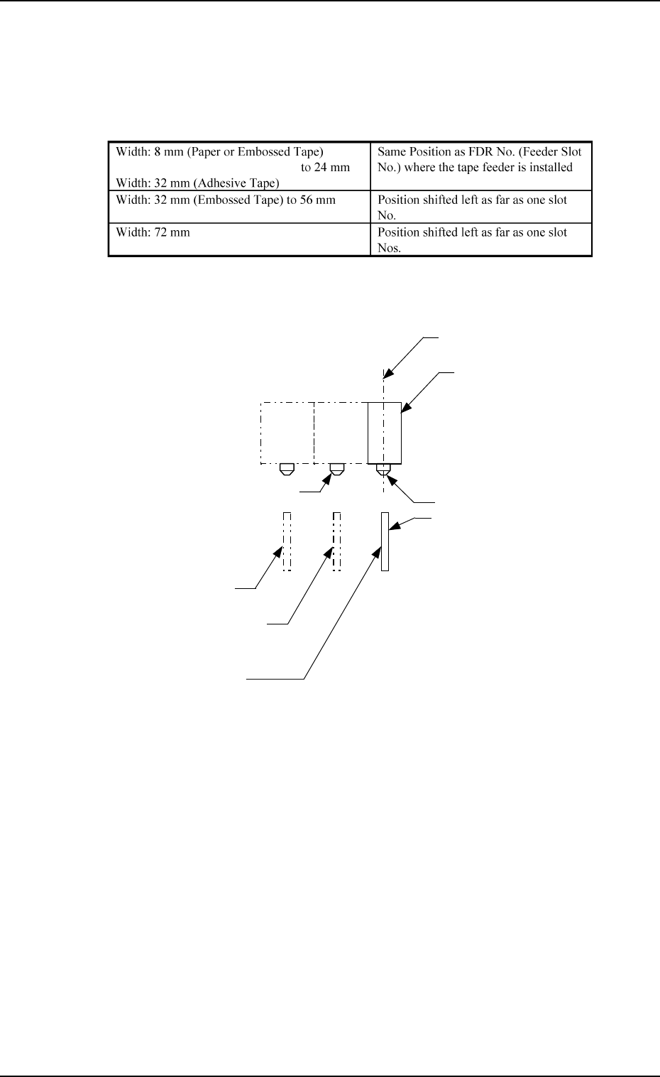
(3) Positional Relation between Tape Feeder Slot No. and Feeder Driv-
ing Lever
Shown in the table below is the position of the feed lever (located on the
feeder base side) which is activated to feed the tape.
Table 1.11
7. Construction of Feeder Carriages
0308-002 1-65 Tg0246-PM-OP
Feed Lever
Tape Feeder
Width: 32 mm (Embossed Tape)
to 56 mm
Locate Pin (Installable FDR No.)
Center of Component
Pick-Up Position
Width: 8 mm (Paper or Embossed Tape)
to 24 mm
Width: 32 mm (Adhesive Tape)
Width: 72 mm
Example:
Fig. 1.31
Note: Shown in Fig. 1.31 is a view based on the direction in which the tape
feeder is installed.
Locate Pin for 72 mm Tape Feeder
(Slot for Feeder Installation)