1OM-1064-002.pdf - 第45页
2. Specifications 9910-001 1-15 Tg0246-PM-OP (3) Lim it of Closest D istance to Obsta cle The close st distances b etwe en an obstacle (See each sectional v iew.) and the vacuum nozzle or com p onent shall b e 0.5 mm or …
2. Specifications
9910-001 1-14 Tg0246-PM-OP
38. Conditions for
Component
Placement
(1) Shape of Vacuum Nozzle
When components are to be placed to the previously-placed components or
the obstacles, the shape of the vacuum nozzle becomes part of the
constraint condition. Refer to “8. Vacuum Nozzles of Section 1 ” for the shapes
of vacuum nozzles.
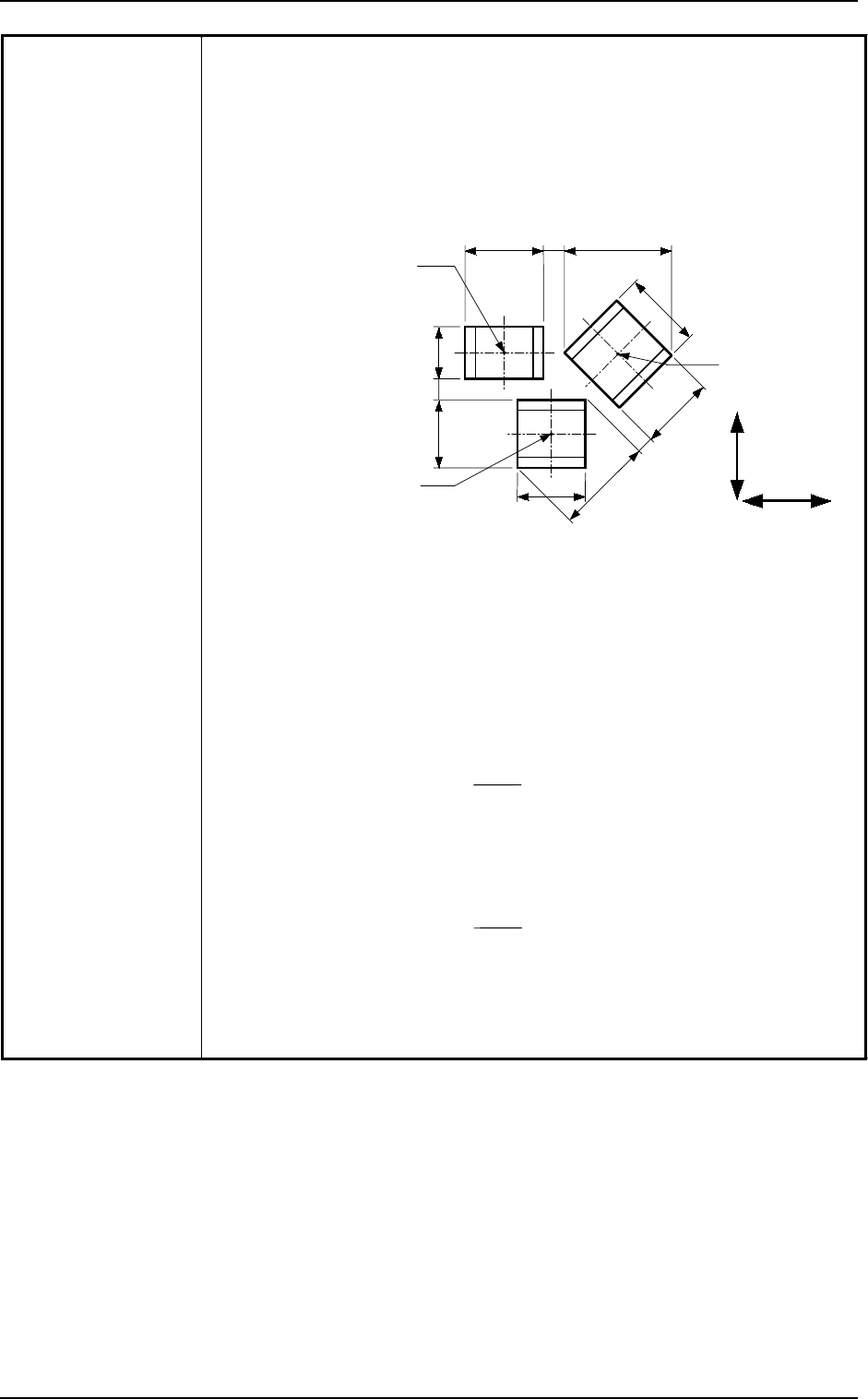
(2) Adjoining Distances between Components
(when the component placement position is taken into consideration)
A
a
G
F
E
b
B
C
c
H
Component
Placement Point 3
Component
Placement Point 2
Component
Placement Point 1
X Direction
Y Direction
Note: (a) The above figure shows that the vacuum nozzles are not protruding
from the outer shapes of components. Consult our sales personnel
for details.
(b) “A to H” in the above figure show the maximum dimensions including
the variations in the dimensions of each component. The minimum
adjoining distances (a, b, and c) of each component should be 0.4 mm.
(c) The minimum adjoining placement position data for component
placement points 1 and 3 is
“X Direction Data = + Min. 0.4 mm”
(The Y direction data is not related.)
(d) The minimum adjoining placement position data for component
placement points 1 and 2 is
“Y Direction Data = + Min. 0.4 mm”
(The X direction data is not related.)
(e) See the above figure and obtain the minimum adjoining placement
position data for component placement points 2 and 3.
B + E
2
A + G
2
2. Specifications
9910-001 1-15 Tg0246-PM-OP
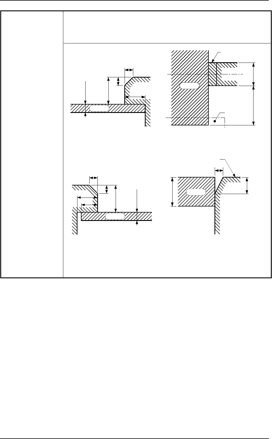
(3) Limit of Closest Distance to Obstacle
The closest distances between an obstacle (See each sectional view.) and
the vacuum nozzle or component shall be 0.5 mm or more. The upper
surface of the P.C.B. is the reference plane.
0.3 to 5
2.5
6.5
1
1
P.C.B.
6
P.C.B.
11
Chute
P.C.B. Stopper
0.3 to 5
2.5
6.5
1
1
P.C.B.
2
0.3 to 5
2
1
P.C.B.
Flush with Upper
Surface of P.C.B.
Unit: mm
Sectional View of
P.C.B. Stopper Section
Sectional View of
Movable Chute Section
Sectional View of
Fixed Chute Section
Top View of P.C.B.
Stopper Section
2. Specifications
9910-001 1-16 Tg0246-PM-OP
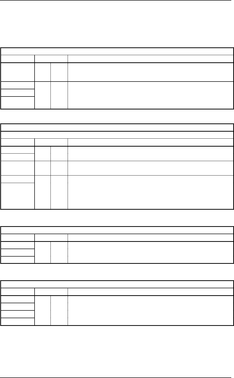
39. Applicable Components for Reference
(1) Taped Components
• Tapes and Reels: JIS/EIAJ or its equivalent
Tape Width : 8 mm
Packaging Standard
Taping Reel Applicable Components for Reference
TP 0802 R08A R08
• Resistors (1.0 × 0.5 mm)
• Other similar-shaped components
TP 0804
TB 0802
TB 0804
R08A R08
• Square Chip-Type Capacitors, Resistors (2 × 1.25 to 3.2 × 2.5 mm)
• Mini-Mold Transistors
• Tantalum Capacitors A
• Other similar-shaped components
Tape Width : 12 mm
Packaging Standard
Taping Reel
Applicable Components for Reference
TP 1204
TP 1208
R12A
R12
TB 1204
R12A
R12
• Tantalum Capacitors B
• Other similar-shaped components
TB 1208
TB 1212
R12A
R12
• Tantalum Capacitors C and D
• Semi-Fixed Potentiometers
• Coils
• Filters
• Other similar-shaped components
Tape Width : 16 mm
Packaging Standard
Taping Reel
Applicable Components for Reference
TB 1604
TB 1608
TB 1612
R16
• Aluminum Electrolytic Capacitors
• Semi-Fixed Potentiometers
• Other similar-shaped components
Tape Width : 24 mm
Packaging Standard
Taping Reel
Applicable Components for Reference
TB 2408
TB 2412
TB 2416
TB 2420
R24
• Connector
• Semi-Fixed Potentiometers
• Other similar-shaped components