1OM-1064-002.pdf - 第85页
6.3.4 TIM-5100RL P .C.B. Reference: R-BACK P .C.B. T ransfer Reference: Rear Side of Machine P .C.B. T ransfer Direction: L → R P .C.B. Positioning Reference: R-BACK 6. Outline of System Operation 9910-001 1-55 Tg0246-PM…
• Selection of “PLACE REF.”
Described below are the actions taken when “PLACE REF.” is set in the
“P.C.B. LOCATE MODE” data box at the “P.C.B. TRANSFER MODE SET-
UP” display. (Hierarchical Sequence: “DATA EDIT” Display → “DEVICE
DATA” Display → “P.C.B. TRANSFER MODE SET-UP” Display).
Note: This function can be used effectively when P.C.B. positioning is
corrected through P.E.C. recognition.
Sufficient accuracy of P.C.B. positioning cannot be expected with-
out P.E.C. recognition.
P.C.B. Transfer Reference: Front Side of Machine
P.C.B. Transfer Direction: R → L
P.C.B. Positioning Reference: R-FRONT
“PLACE REF.”
6. Outline of System Operation
9910-001 1-54 Tg0246-PM-OP
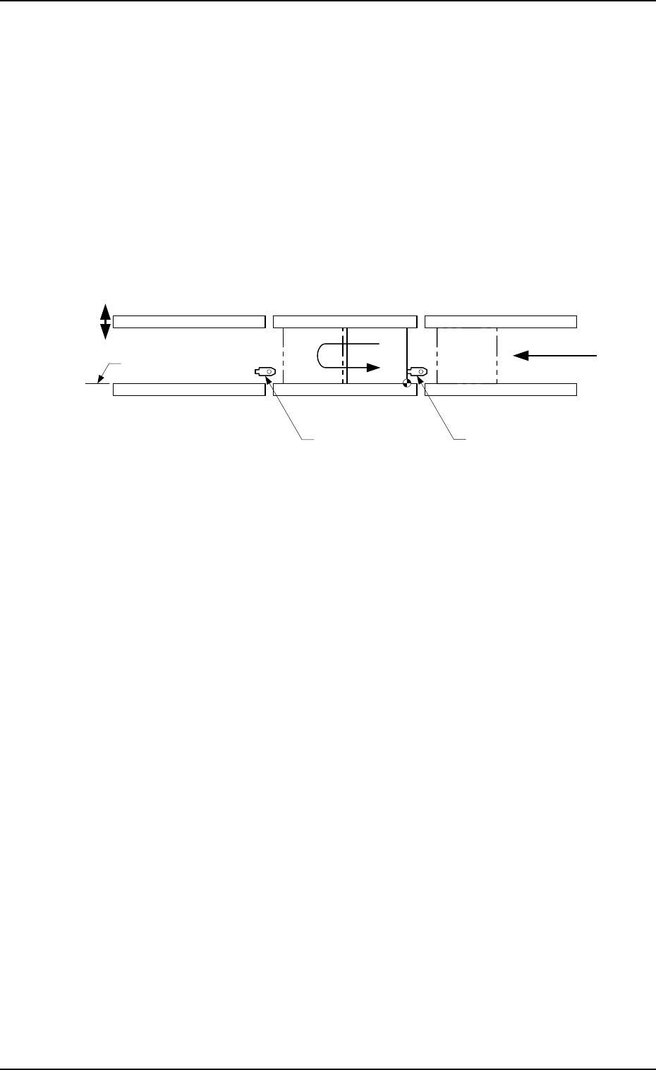
Fig. 1.23-3
Outline of System Operation
(1) The P.C.B. transferred from the input machine is sent to the P.C.B. stop-
per of the R conveyor and stops there.
(2) After the P.C.B. at the P.C.B. positioning section has been discharged, the
P.C.B. stopper of the R conveyor descends and the P.C.B. at position A is
transferred ahead of the P.C.B. stopper of the R conveyor.
(3) The P.C.B. stopper of the R conveyor rises and then the P.C.B. is returned
to the P.C.B. stopper of the R conveyor and stops there.
(4) The backup base rises and works to position the P.C.B. vertically and
align it in the Y direction.
The amount of the backup base rise is numeric-controlled by the servo-
motor.
(5) The P.C.B. is positioned in Y direction.
(6) After the P.C.B. positioning has been completed, the machine stars the
P.E.C. recognition operation and component placement.
(7) After the placement operation has been completed, the positioning is can-
celled, the backup base descends, and the P.C.B. is transferred to the L
conveyor.
(8) When the backup base lowering has been completed, the P.C.B. discharged
onto the L conveyor is transferred to the output machine, using the L
conveyor.
R Conveyor
(Input Conveyor)
L Conveyor
(Output Conveyor)
L Conveyor
P.C.B. Stopper
R Conveyor
P.C.B. Stopper
P Conveyor
(P.C.B. Positioning Section)
Movable Side
P.C.B.
P.C.B. Flow Direction
P.C.B. Transfer Reference
A
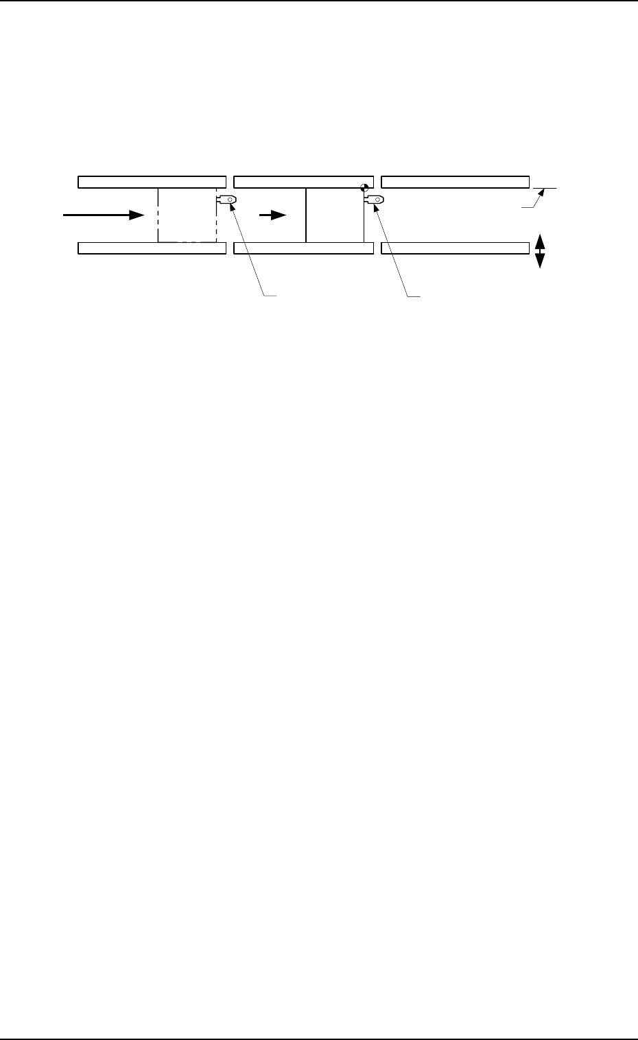
6.3.4 TIM-5100RL
P.C.B. Reference: R-BACK
P.C.B. Transfer Reference: Rear Side of Machine
P.C.B. Transfer Direction: L → R
P.C.B. Positioning Reference: R-BACK
6. Outline of System Operation
9910-001 1-55 Tg0246-PM-OP
Fig. 1.24-1
Outline of System Operation
(1) The P.C.B. transferred from the input machine is sent to the P.C.B. stop-
per of the L conveyor and stops there.
(2) After the P.C.B. at the P.C.B. positioning section has been discharged, the
P.C.B. stopper of the L conveyor descends and the P.C.B. at position A is
transferred to the P.C.B. stopper of the R conveyor.
(3) The backup base rises and works to position the P.C.B. vertically and to
align it in the Y direction.
The amount of the backup base rise is numeric-controlled by the servo-
motor.
(4) After the P.C.B. positioning has been completed, the machine starts the
P.E.C. recognition operation and component placement.
(5) After the placement operation has been completed, the positioning is can-
celled, the backup base descends, the P.C.B. stopper of the R conveyor
also descends, and the P.C.B. is transferred to the R conveyor.
(6) When the backup base lowering has been completed, the P.C.B. discharged
onto the R conveyor is transferred to the output machine, using the R
conveyor.
L Conveyor
(Input Conveyor)
R Conveyor
(Output Conveyor)
L Conveyor
P.C.B. Stopper
R Conveyor
P.C.B. Stopper
P Conveyor
(P.C.B. Positioning Section)
Movable Side
P.C.B.
P.C.B. Flow Direction
P.C.B. Transfer Reference
A
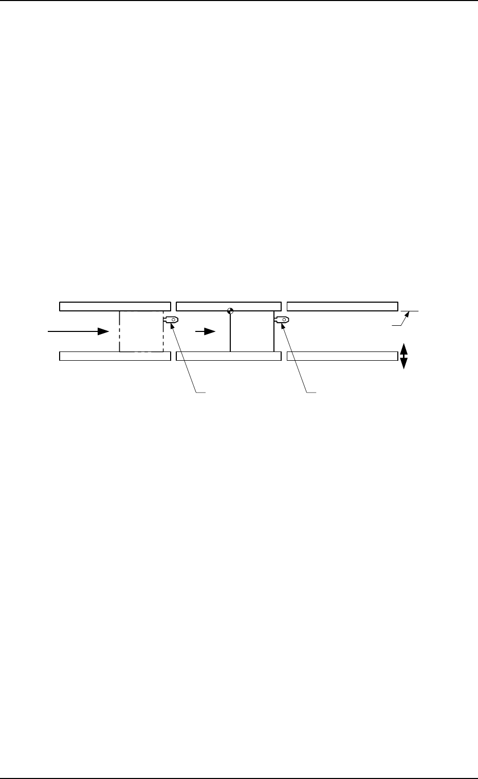
P.C.B. Reference: L-BACK
“PLACE REF.” or “PRI PCB STR” can be selected.
Refer to “2. P.C.B. TRANSFER MODE SET-UP Display of Section 3 in Vol-
ume 2” for details.
• Selection of “PRI PCB STR”
Described below are the actions taken when “PRI PCB STR” is set in the
“P.C.B. LOCATE MODE” data box at the “P.C.B. TRANSFER MODE SET-
UP” display. (Hierarchical Sequence: “DATA EDIT” Display → “DEVICE
DATA” Display → “P.C.B. TRANSFER MODE SET-UP” Display).
Note: This function can be used effectively when P.C.B. positioning is
corrected through P.E.C. recognition.
Sufficient accuracy of P.C.B. positioning cannot be expected with-
out P.E.C. recognition.
P.C.B. Transfer Reference: Rear Side of Machine
P.C.B. Transfer Direction: L → R
P.C.B. Positioning Reference: L-BACK
“PRI PCB STR”
6. Outline of System Operation
9910-001 1-56 Tg0246-PM-OP
L Conveyor
(Input Conveyor)
R Conveyor
(Output Conveyor)
L Conveyor
P.C.B. Stopper
R Conveyor
P.C.B. Stopper
P Conveyor
(P.C.B. Positioning Section)
Movable Side
P.C.B.
P.C.B. Flow Direction
P.C.B. Transfer Reference
A
Fig. 1.24-2
Outline of System Operation
(1) The PCB transferred from the input machine is sent to the P.C.B. stopper
of the L conveyor and stops there.
(2) After the P.C.B. at the P.C.B. positioning section has been discharged, the
P.C.B. stopper of the L conveyor descends and the P.C.B. at position A is
transferred to the P.C.B. stopper of the R conveyor.
(3) The backup base rises and works to position the P.C.B. vertically and to
align it in the Y direction.
The amount of the backup base rise is numeric-controlled by the servo-
motor.
(4) After the P.C.B. positioning has been completed, the machine starts the
P.E.C. recognition operation and component placement.
(5) After the placement operation has been completed, the positioning is can-
celled, the backup base descends, the P.C.B. stopper of the R conveyor
also descends, and the P.C.B. is transferred to the R conveyor.
(6) When the backup base lowering has been completed, the P.C.B. discharged
onto the R conveyor is transferred to the output machine, using the R
conveyor.