1OM-1064-002.pdf - 第101页
1. Notes • Either the front or the rear panel can be set available in operation by press- ing the [PNL CHANGE] button on the unavailable side only when both are not in “LOCK” mode. Either one of the operation panels can …

1. Notes
1. Notes
1.1 [PNL CHANGE] Buttons
• The front and rear operation panels are provided with a [PNL CHANGE]
button.
• Operations are performed with the keys on the touch screen and the buttons
and switches on the operation panels. To avoid any danger, either one of the
front and rear operation panels including the touch screens can be set avail-
able in operation.
• It is impossible to activate both operation panels, including the touch screen
at the same time.
• When one of the operation panels is active (set available in operation), the
LED (-HD05) of the [PNL CHANGE] button illuminates. (Operation Pos-
sible)
• When one of the operation panels is not active, the LED (-HD05) of the
[PNL CHANGE] button extinguishes. (Operation Impossible)
• Listed below are valid buttons when the [PNL CHANGE] button is pressed.
Touch Screen Switch
[START] Button
[RESET] Button
[ZERO] Button
[MOVE] Button
[SYS CLR] Button
• The following buttons can be activated anytime regardless of the [PNL
CHANGE] buttons.
[STOP] Button
[PAUSE] Button
• When the [PNL CHANGE] button on the available operation panel is pressed,
the LED (-HD05) of the button goes on and the LED (-HD06) illuminates,
indicating that the operation is locked.
• When the LED (-HD06) on the front panel illuminates, the LED (-HD06) on
the rear panel also goes on.
• When the operation is locked, the [PNL CHANGE] buttons become un-
available.
• To cancel “LOCK” mode, press the [PNL CHANGE] button on the avail-
able side again.
“LOCK” mode is canceled and the LED (-HD06) extinguishes.
• When the [SYS CLR] button on the operation panel in “LOCK” mode is
pressed, the “LOCK” mode is canceled.
9910-001 2-2 Tg0246-PM-OP
1. Notes
• Either the front or the rear panel can be set available in operation by press-
ing the [PNL CHANGE] button on the unavailable side only when both are
not in “LOCK” mode.
Either one of the operation panels can be selected regardless of the opera-
tion mode (such as “RUN” and “PAUSE”) of the machine.
9910-001 2-3 Tg0246-PM-OP
CAUTION
When the [STOP] or the [PAUSE] button is pressed with the operation
lock LED (-HD06) OFF, the operation panel on the pressed button side is
automatically set available in operation.
• When the [OPERATION/SET UP] switch on the available side is set to the
“SET UP” side, the unavailable side is locked forcibly.
Note: When the [OPERATION/SET UP] switch on the unavailable side is
pressed, an error occurs.
To cancel the “LOCK” mode, set the [OPERATION/SET UP] switch to the
“OPERATION” side.
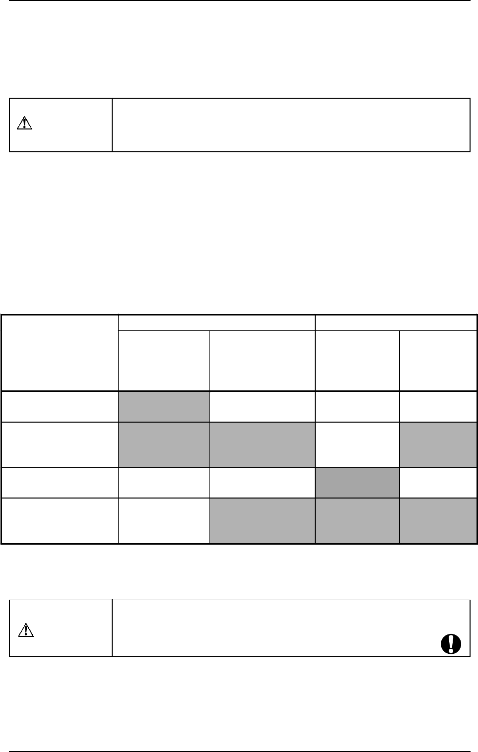
• Described in the table below is the ON/OFF relation between the LED (-
HD05) of the [PNL CHANGE] button and the operation lock LED (-HD06).
Table 2.1
Note: When power is supplied, the front operation panel including the touch
screen is set available in operation.
Front Operation Panel Rear Operation Panel
Mode
LED (-HD05) of
[PNL CHANGE]
Button
Operation Lock
LED (-HD06)
LED (-HD05)
of [PNL
CHANGE]
Button
Operation
Lock LED
(-HD06)
Front Panel Available in
Operation
ON OFF OFF OFF
Operations Available
Only with Front Panel
(Operation Locked)
ON ON OFF ON
Rear Panel Available in
Operation
OFF OFF ON OFF
Operations Available
Only with Rear Panel
(Operation Locked)
OFF ON ON ON
CAUTION
In principle, the machine must be operated by only one person.
If there are more than one, ensure good communication by giving loud
verbal instructions for safety purposes.
1. Notes
WARNING
1. Do not keep the selection key inserted unless necessary. The key
shall be stored by the person in charge.
2. Only the trained personnel shall operate the machine when the [OP-
ERATION/SET UP] switch is set to the “SET UP” side. Otherwise, it
may cause critical injury to the operator.
3. When the [OPERATION/SET UP] switch is set to the “SET UP” side,
the operator can operate the machine with the maintenance cover
open.
It is very dangerous to operate the machine without safety check. Be
sure to pay a special caution while operating the machine.
The [OPERATION/SET UP] switch must be kept in the “OPERATION”
side in normal cases to avoid any danger.
1.2 [OPERATION/SET UP] Switch
When the [OPERATION/SET UP] switch is set to the “SET UP” side, the
interlock functions of the maintenance/supply cover and the safety bar are
partly canceled, making it possible to perform set-up operations with the main-
tenance cover opened (limited to the actions taken without any X/Y beam move-
ment).
0004-002 2-4 Tg0246-PM-OP
• The [OPERATION/SET UP] switch becomes effective only when the fol-
lowing requirements are fulfilled.
(1) The machine must be set in the “STOP” mode.
(2) Operations must be performed on the operation available side.
(3) The maintenance/supply cover and the safety bar on the operation un-
available side must be closed.
(4) The up/down axis (LA1, LA2, LB1, and LB2 axis) on each beam must
be located at their origins (NEAR).
• The selection key must be used to change over the [OPERATION/SET UP]
switch.
• When the [OPERATION/SET UP] switch is set to the “SET UP” side, all
tower lights (red, yellow, and green) illuminate.
• When the [OPERATION/SET UP] switch is set to the “SET UP” side, the
power to drive the X/Y beam is shut off.