1OM-1064-002.pdf - 第95页
(3) Positional Relation between T ape Feeder Slot No. and Feeder Driv- ing Lever Shown in the table below is the position of the feed lever (located on the feeder base side) which is activated to feed the tape. T able 1.…
7. Construction of Feeder Carriages
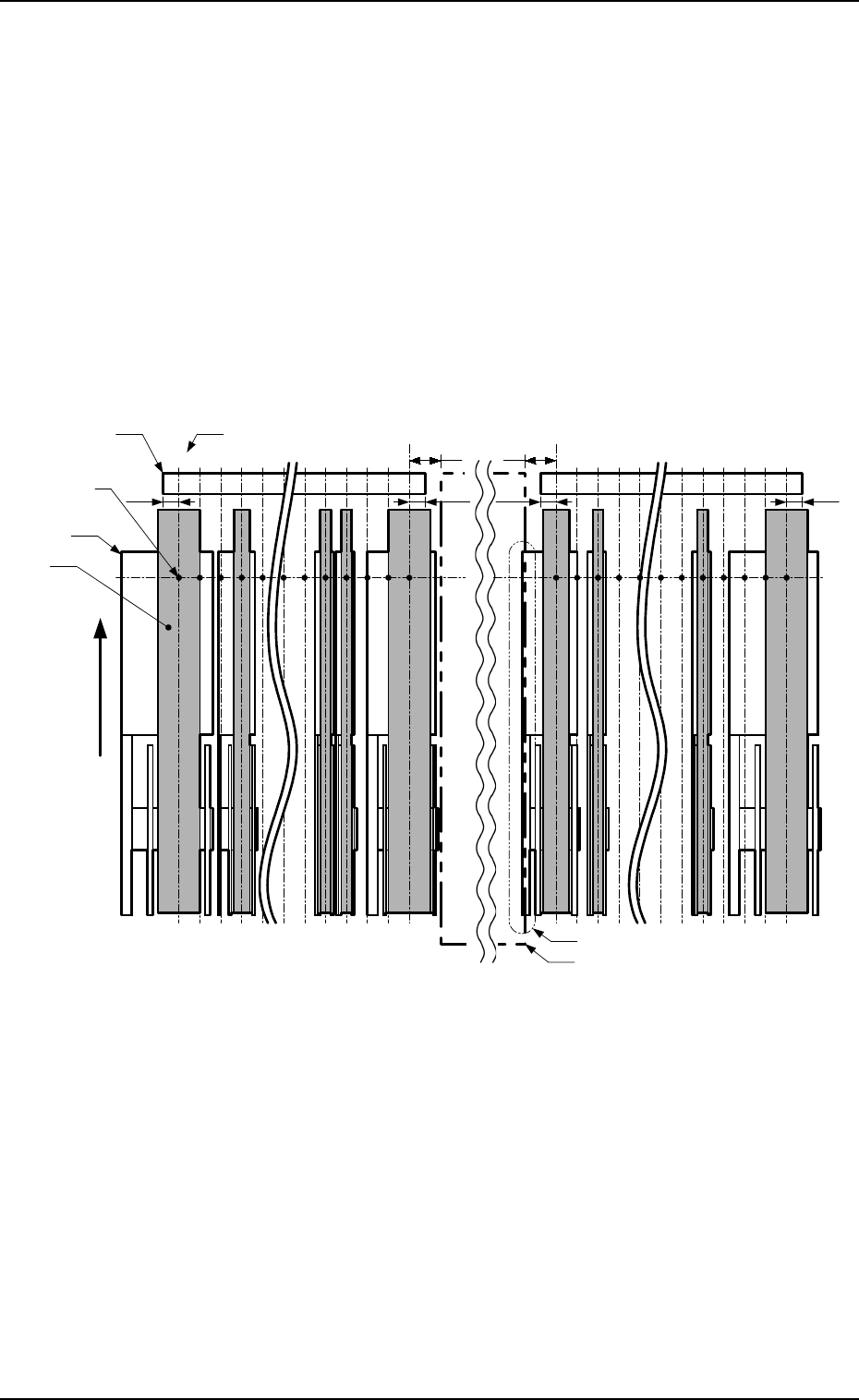
Example: Fig. 1.30 shows how tape feeders are installed on the feeder bases.
• FDR No. *01
The tape feeder cannot be installed on the feeder base because the tape
interferes with the tape guide when the tape is fed out.
• FDR No. *19
The tape feeder cannot be installed on the feeder base because it inter-
feres with the rejected component storage box or the component dis-
charge conveyor (option).
• FDR No. *21
The tape feeder cannot be installed on the feeder base because the tape
interferes with the tape guide when the tape is fed out.
• FDR No. *39
The tape feeder cannot be installed on the feeder base because the tape
interferes with the tape guide when the tape is fed out.
7.3
*39
Tape Feeder
Center of Component
Pick-Up Position
Rejected Component Storage Box or
Component Discharge Conveyor (Option)
7.3
*21
*23*25*37 *35 *01*03*05
*19
*17 *15
FDR No. (Feeder Slot No.)
Tape
Tape Guide
10 10
Left Side
7.37.3
User Direction of
Tape Feed
(Direction of
Unreeling the Tape)
Right Side
Interference (Installation Impossible
)
Fig. 1.30
9910-001 1-64 Tg0246-PM-OP
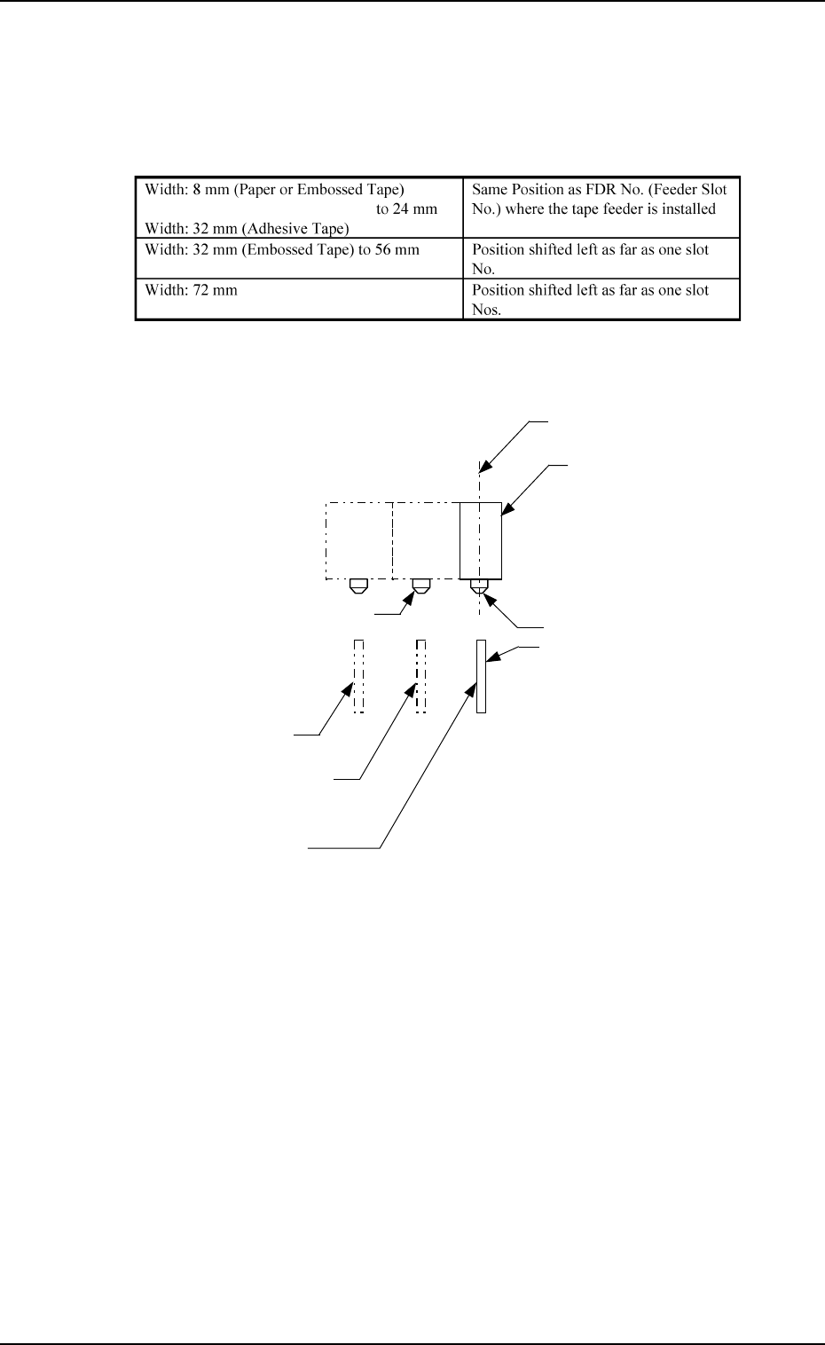
(3) Positional Relation between Tape Feeder Slot No. and Feeder Driv-
ing Lever
Shown in the table below is the position of the feed lever (located on the
feeder base side) which is activated to feed the tape.
Table 1.11
7. Construction of Feeder Carriages
0308-002 1-65 Tg0246-PM-OP
Feed Lever
Tape Feeder
Width: 32 mm (Embossed Tape)
to 56 mm
Locate Pin (Installable FDR No.)
Center of Component
Pick-Up Position
Width: 8 mm (Paper or Embossed Tape)
to 24 mm
Width: 32 mm (Adhesive Tape)
Width: 72 mm
Example:
Fig. 1.31
Note: Shown in Fig. 1.31 is a view based on the direction in which the tape
feeder is installed.
Locate Pin for 72 mm Tape Feeder
(Slot for Feeder Installation)
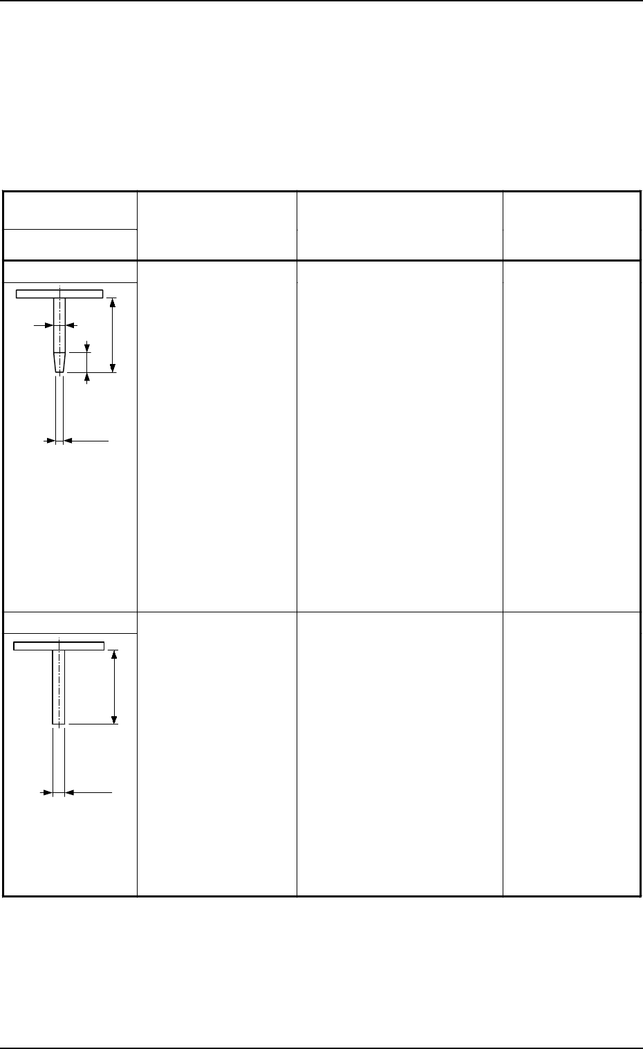
8. Vacuum Nozzles
8. Vacuum Nozzles
List of Nozzle Types
The machine is equipped with vacuum nozzles designated in the delivery speci-
fications at shipment.
Unit: mm
Table 1.1
2
9910-001 1-66 Tg0246-PM-OP
Code
Nozzle Type
(a)
Component Size
(Referential Values)
(
mm
)
(
b
)
Applicable Components
(For Reference)
Part No.
Part Name
MA04
19
3
4.5
Inside Diameter
φ
1.1
Outside Diameter
φ
1.8
2.5
×
2.0 to 4.0
×
4.0
Capacitors and Resistors of 3225
to 6432 Types
Network Resistors of 2520 Type
Inductors of 4525 Type
Horn Tantalum Capacitors of
3427 to 4527 Types
Tantalum Electrolytic Capacitors
A, B, and B2
Ferrite Chip Beads of 3216 to
4532 Types
LEDs (2924 to 3427)
Transistors (4525)
Diodes of 4525 to 4738 Types
Aluminum Electrolytic Capacitors
(φ3)
Coils (2.5 × 2.5 to 4 × 4)
Filters (4532)
Oscillators (7.2 × 2.8 × 2.5)
Trimmer Capacitors
Semi-Fixed Variable Resistors
Other similar-shaped components
630 075 9044
NOZZLE (MA04)
MA05
19
Inside Diameter
φ
2.0
Outside Diameter
φ
3.0
4.0
×
4.0 to 12.5
×
5.5
Capacitors and Resistors of 4532
to 5780 Types
Inductors of 5650 Types
Horn Tantalum Capacitors of
5644 to 5646 Types
Tantalum Electrolytic Capacitors
B, C, D, G, N
Aluminum Electrolytic Capacitors
(φ4, φ5)
Coils (4 × 4 to 6 × 6)
Filters, Single, Double, Triple
Oscillators (7.3 × 5.0 × 2.6)
Trimmer Capacitors
Semi-Fixed Variable Resistors
Switches
SOP, SOJ 8 to 16 Pins
Other similar-shaped components
630 075 9051
NOZZLE (MA05)