1OM-1064-002.pdf - 第63页
5. Operation Panel (Names and Functions) 9910-001 1-33 Tg0246-PM-OP T able 1.2- 2 Switch Name Symbol Function ZERO -SPB13 (-HD 03) • Zeroes all devices possible to be zeroed. While the LE D is ON, it indicates that the d…
Switch Name
Symbol Function
POWER ON -SPB01
(-HD50)
•
Supplies the power for operation.
The red LED illuminates when only power for operation is supplied.
The green LED illuminates when power for both operation and loads is
supplied.
POWER OFF -SPB03
• Turns off the power for operation.
Turning the lock type switch clockwise shuts off the power.
OPERATION
SET UP
-S01
•
Changes over the switch from “OPERATION” to “SET UP” or vice
versa.
•
SYS CLR -SPB18
•
Clears the system to the initial setting or cancels an operation.
Note: When the [SYS CLR] button is pressed at the [OPERATION/SET
UP] switch set to the “SET UP” side, the system cannot be
cleared.
START -SPB11
(-HD01)
•
Starts automatic operation of the machine.
While the LED is ON, it indicates that the machine is running
automatically.
It extinguishes when the machine is stopped during operation.
STOP -SPB15
• Stops automatic operation of the machine.
It is possible to stop the automatic operation with this switch during
the X/Y beam test.
• When this button is pressed during zeroing operation, each individual
devices are stopped.
PAUSE -SPB16
• Stops automatic operation temporarily.
It is possible to temporarily stop the automatic operation with this
switch during the X/Y beam test.
• When this button is pressed during zeroing operation, each individual
devices are stopped temporarily.
RESET -SPB17
• Releases an error signal and resumes the power (Power ON) for the
servomotor driver.
READY -SPB31
(-HD09)
Front Operation Panel
This button is used to tell the machine that the feeders such as tape and
stick feeders on the front side (Side B) are ready for replacement.
• Refer to “5.5 [READY] Button of Section 1” for details.
Rear Operation Panel
• This button is used to tell the machine that the feeders such as tape and
stick feeders on the rear side (Side A) are ready for replacement.
• Refer to “5.5 [READY] Button of Section 1” for details.
BUZZER -HA01
• Sounds when an error occurs.
When the switch is changed to “SET UP”,
the interlock functions of the safety door,
etc., are deactivated.
Do not set this switch to “SET UP” except
for a set-up operation.
Refer to “1.2 [OPERATION/SET UP]
Switch of Section 2” for details.
WARNING
Table 1.2-1
9910-001 1-32 Tg0246-PM-OP
5. Operation Panel (Names and Functions)

5. Operation Panel (Names and Functions)
9910-001 1-33 Tg0246-PM-OP
Table 1.2-2
Switch Name Symbol Function
ZERO -SPB13
(-HD03)
•
Zeroes all devices possible to be zeroed.
While the LED is ON, it indicates that the devices are being zeroed.
Note: When the [ZERO] button is pressed with the [OPERATION/SET
UP] switch set to the "SET UP" side, each individual devices
cannot be zeroed.
MOVE -SPB12
(-HD02)
•
Executes the functions labeled on the touch screen.
While the LED is ON, it indicates that the selected function is being
activated..
PNL CHANGE -SPB19
(-HD05)
Front Operation Panel
•
Activates the front or rear operation panel.
While the LED (-HD05) is ON, functions can be implemented through
the front operation panel and the front touch screen.
•
When the button is pressed while the LED (-HD05) is ON (panel
activated), only the front panel becomes available (operation locked)
and the LEDs (operation lock -HD06) of both front and rear panels
illuminate.
•
To cancel the locked operation, press the button again.
Rear Operation Panel
•
Activates the front or rear operation panel.
While the LED (-HD05) is ON, functions can be implemented through
the rear operation panel and the rear touch screen.
•
When the button is pressed while the LED (-HD05) is ON (panel
activated), only the rear panel becomes available (operation locked)
and the LEDs (operation lock -HD06) of both front and rear panels
illuminate.
•
To cancel the locked operation, press the button again.
LOCK -HD06
•
While the LED is ON, the selected operation is locked.
SERVO
POWER
HD51B
HD51A
Front Operation Panel
•
Shows whether or not the load power for XB and YB axis (X/Y axis
on the front side) is supplied.
•
While the LED is ON, it indicates that power is supplied to the
servomotors for the XB and YB axis.
Rear Operation Panel
•
Shows whether or not the load power for XA and YA axis (X/Y axis
on the rear side) is supplied.
•
While the LED is ON, it indicates that power is supplied to the
servomotors for the XA and YA axis.
EMERGENCY
STOP
SPB52
(Front)
SPB53
(Rear)
•
Stops the automatic operation immediately in an emergency.
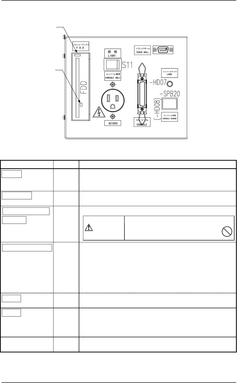
5.3 Front Console Panel
Name Symbol Function
LIGHT
S11
•
This switch is used to turn on or off the illuminating lamps for
the component placement section and a P.C.B.
• Turns on or off the work lamp on Side B (front side).
CONSOLE
X8
•
This connector is used to link a programming device (option) for
data communication.
CONSOLE ONLY
AC100V
X11
•
This outlet is used only for the programming device (option).
CONSOLE CHANGE
-SPB20
(-HD08)
• This button is used to select either the front or the rear serial port
for external communication of the console.
•
When the button is pressed while -HD08 is ON (console
activated), only the front console becomes available (console
locked) and the LEDs (-HD07 on the front and rear sides)
illuminate.
• To cancel the locked console, press the button again.
LOCK
(-HD07)
• While -HD07 is ON, it indicates that front and rear consoles are
locked.
F.D.D.
FDD
• Floppy Disk Drive
Do not press the eject button when the access lamp is ON.
Otherwise, the data stored on the inserted floppy disk may be
corrupted.
TRACK BALL
XCN146
•
This port is used to connect a trackball for component library
teaching operation (option), etc.
Do not connect any other device except
the programming device (option)
to this outlet.
CAUTION
5. Operation Panel (Names and Functions)
0004-002 1-34 Tg0246-PM-OP
Fig. 1.11
Table 1.3
Eject Button
Access Lamp