1OM-1064-002.pdf - 第72页
9910-001 1-42 Tg0246-PM-OP 6. Outline of System Operation (2) Front Lighting Recognition System Fig. 1.18 shows the sectional view of the recognition unit and the flow of the recognition light in the front lighting recog…
6. Outline of System Operation
9910-001 1-41 Tg0246-PM-OP
6.2.2 Principle of Recognition
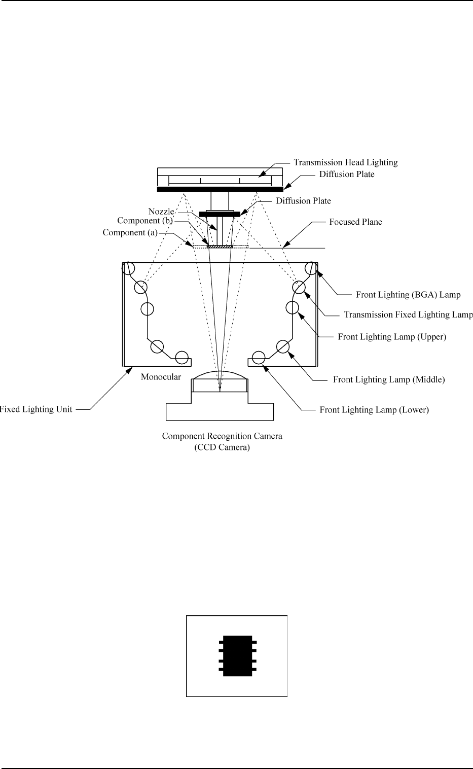
(1) Back Lighting Recognition System
Fig. 1.16 shows the sectional view of the recognition unit and the flow of
recognition light in the back lighting recognition system.
• As for component (a) shown by the dotted line, the outline is recog-
nized through transmission head lighting.
• As for component (b) shown by the diagonal lines, the outline is rec-
ognized through transmission fixed lighting.
Fig. 1.16
The light emitted from the transmission head lighting meets the diffusion plate
(assembled together with the nozzle) and reflects to the component. At this
time, the light which does not meet the component enters into the CCD camera
through the monocular.
The light discharged from the transmission fixed lighting goes through the
diffusion plate and meets the component. The light which is not interrupted by
the component enters into the CCD camera through the monocular.
That is, the CCD camera captures the image of the outline of the component.
Fig. 1.17 Image (Example) on Recognition Monitor
9910-001 1-42 Tg0246-PM-OP
6. Outline of System Operation
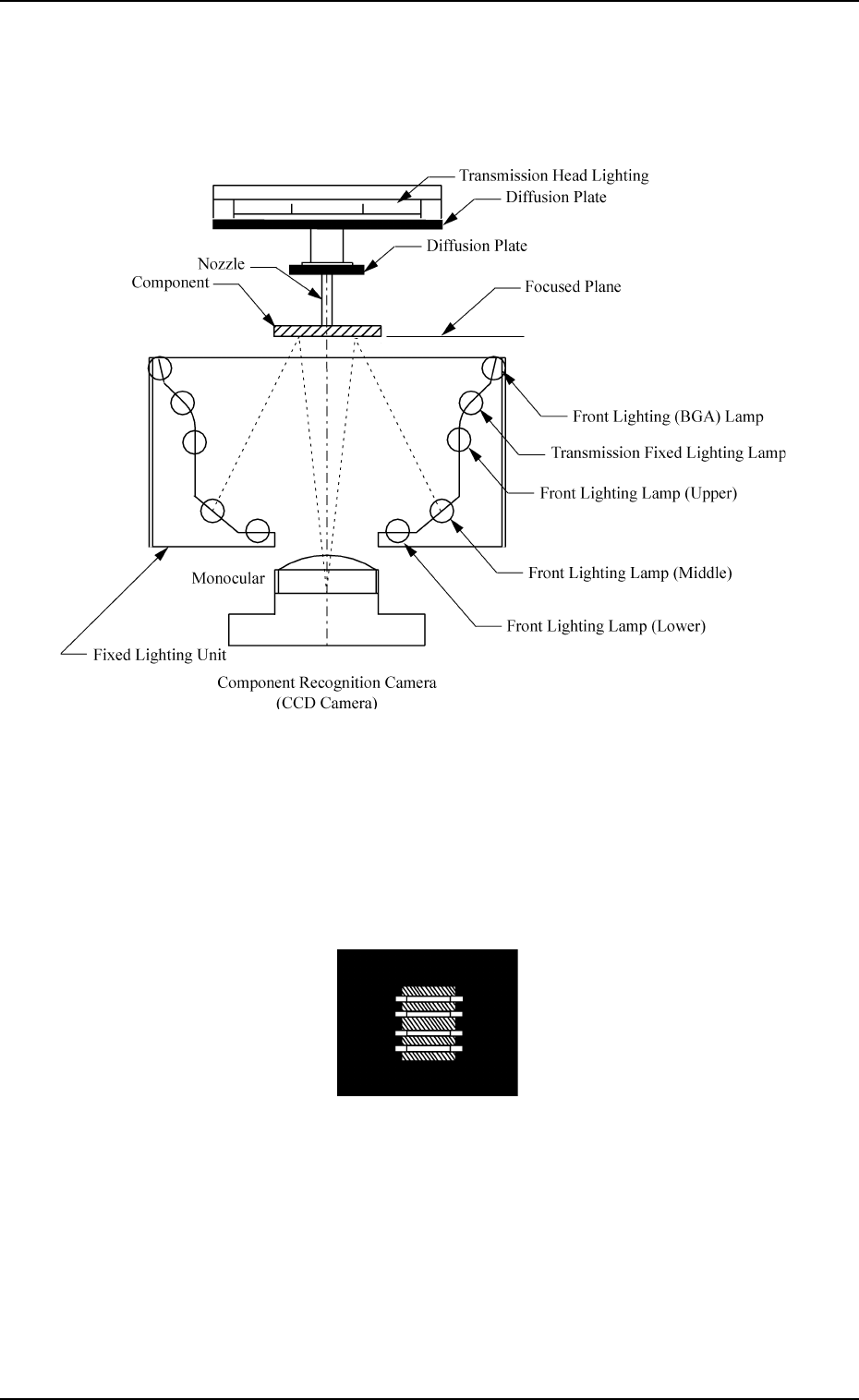
(2) Front Lighting Recognition System
Fig. 1.18 shows the sectional view of the recognition unit and the flow of
the recognition light in the front lighting recognition system. Select the
proper lighting system, using the front lighting lamps (upper, middle, and
lower) for component recognition.
Fig. 1.18
The light emitted from the front lighting lamps (upper, middle, and lower)
meets the bottom of the component.
The reflected light enters into the CCD camera through the monocular.
That is, the CCD camera captures the image of the component leads, etc.
Fig. 1.19 Image (Example) on Recognition Monitor
Recognition Method
Applicable Component Size
Image Scanning
Method
Lighting to be
Used
Small View Large View Maximum View
Front Lighting
1.0 × 0.5 to
23 × 15 mm
2.0 × 1.2 to
46 × 34 mm
2.0 × 1.2 to
46 × 46 mm
Batch
Back Lighting
1.0 × 0.5 to
23 × 15 mm
2.0 × 1.2 to
36 × 35 mm
2.0 × 1.2 to
36 × 36 mm
Divided Front Lighting
Max. 55 × 55 mm Max. 55 × 55 mm
Note
Max. 55 × 55 mm
Note
6. Outline of System Operation
9910-001 1-43 Tg0246-PM-OP
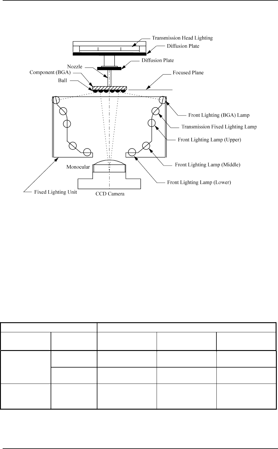
(3) Front Lighting (BGA) System
Fig. 1.20 shows the sectional view of the recognition unit and the flow of
the recognition light in the front lighting (BGA) system.
Fig. 1.20
The light emitted from the front lighting for BGA meets the balls, etc., on the
bottom of the BGA component. The reflected light enters into the CCD cam-
era through the monocular. The captured images look like doughnuts. That is,
the CCD camera can be used to detect where the BGA balls are located or
whether or not the balls exist.
Supplement:
• One of the three fields of view can be selected for the component recogni-
tion camera.
Two cameras are installed on each beam. (4 cameras in total)
As a standard combination of cameras, four large view cameras are recom-
mended.
Note: In the case of the connector, this recognition can be applied to Max.
150 × 26 mm.
Table 1.5