1OM-1064-002.pdf - 第144页
5. Preparation and Confirmation before Operation (4) Press the pertinent “FDR.” key or the [ALL CLEAR] key E to select the objective parameters. In the case of tray feeders (option), press each “BLK.” key . • Select the …
5. Preparation and Confirmation before Operation
E
F
G
D
Operation Procedure
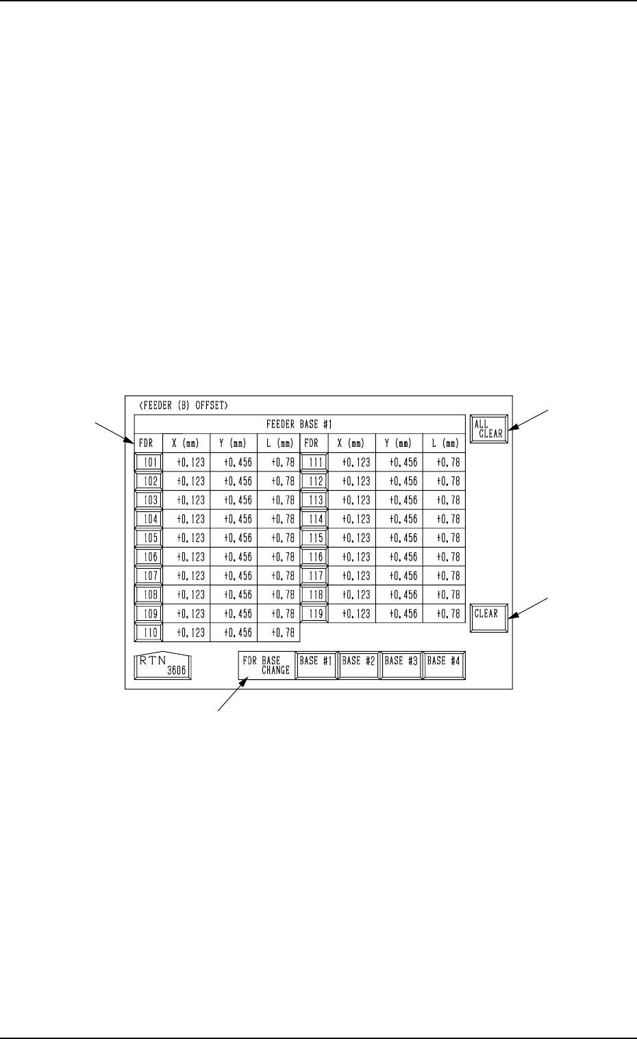
(1) Select the line of offset parameters to be changed or deleted by pressing
the corresponding “FDR.” key at the “FEEDER (B) OFFSET” display
(Fig. 2.27, 2.28, or 2.29).
Part of the display layout differs depending on the selected type of feed-
ers.
(2) Select how to change or clear the offset data.
• To change or clear the offset data individually
*1 Select the required key.
*2 Enter a parameter and press the [SET] key. The entered parameter is
defined.
• To clear the offset data individually (for each individual feeders) or all
the offset data at a time, proceed to Step (3).
(3) Press the [DATA CLEAR] key A at the “FEEDER (B) OFFSET” display.
Another “FEEDER (B) OFFSET” display appears on the screen, enabling
you to clear the offset data.
0004-002 2-45 Tg0246-PM-OP
Fig. 2.30

5. Preparation and Confirmation before Operation
(4) Press the pertinent “FDR.” key or the [ALL CLEAR] key E to select the
objective parameters.
In the case of tray feeders (option), press each “BLK.” key.
• Select the feeder base where the data to be cleared belong by pressing
the [BASE #1], the [BASE #2], the [BASE #3], or the [BASE #4] key
D.
Ref.: The desired feeder base can be selected in the selection B at
the “FEEDER (B) OFFSET” display.
• Press the [ALL CLEAR] key to clear all the data.
When the [ALL CLEAR] key is pressed, it turns red and the “FDR.”
keys G turn blue.
• To clear each data individually, select the pertinent “FDR.” key G. The
selected “FDR.” key turns blue.
• To cancel the all data clear mode, press the [ALL CLEAR] key again
before the [CLEAR] key.
(The [ALL CLEAR] key in red turns normal.)
(5) Press the [CLEAR] key F. The offset data of the selected feeder is cleared
to “0” (zero).
Ref.: When the [TEACHING] key C is pressed, another “FEEDER (B) OFF-
SET” display appears on the screen for teaching operations.
Note: Never modify the parameters set at the “FEEDER (A) OFFSET” dis-
play described in “3. FEEDER (A) OFFSET and FEEDER (B) OFF-
SET Displays of Section 5 in Volume 2”.
This data is used independently for the machine. If the data is modified
carelessly, components may not be picked up from the feeders.
0004-002 2-46 Tg0246-PM-OP

5. Preparation and Confirmation before Operation
5.3 Pattern Program Checking for Production Model
5.3.1 Setting and Checking of P.C.B. Recognition
P.E.C. Recognition Function
The P.E.C. camera checks the coordinates of fiducial marks (2 or 3 places) on
the P.C.B. and determines the deviation from theoretical coordinates.
Furthermore, this function is used in the actual production, the positional de-
viations of the placed components are automatically corrected.
Refer to “2.3.2 Operation Data (P.E.C. Recognition) of Section 2 in Volume 2”
for details.
When “ON” is set in the “P.E.C. RECOGNITION” data box at the “OPERA-
TION DATA” display, follow the procedure below to prepare for automatic
operation.
Operation Procedure
(1) Turn on the “P.E.C. RECOG LIGHT” switch on the console panel and
then turn off the “LIGHT” switch.
(2) Prepare a P.C.B. to be used for actual production and make a P.E.C. rec-
ognition test to verify each set parameters.
Refer to “7.1 P.E.C. RECOG TEST Display of Section 3 in Volume 4” for
details on the P.E.C. recognition test.
(2.1) Whenever the parameters set in the “MARK TYPE”, “MARK
SIZE”, “WINDOW SIZE”, “RECOGNITION ALGORITHM”,
“MARK IMAGE”, and “MARK LEVEL” data boxes are
changed, be sure to modify the original pattern program data.
Refer to “4. PATTERN PROGRAM Display of Section 2 in
Volume 2” for details on how to modify the pattern program data.
(2.2) Determine the gain and level data of Camera #3 (for P.E.C.
recognition). The determined gain and level must be entered in
the offset data.
Refer to “10. P.E.C. RECOG CAMERA OFFSET Display of
Section 5 in Volume 2” for details on the offset data.
5.3.2 Confirmation of Placement Position
Perform an X/Y beam test to verify that the component placement position is
correct.
Refer to “7.3 X/Y BEAM TEST Display of Section 3 in Volume 4” for details.
0004-002 2-47 Tg0246-PM-OP