1OM-1064-002.pdf - 第61页
5. Operation Panel (Names and Functions) 0304-002 1-31 Tg0246-PM-OP Fig. 1.10 5.2 Front and Rear Operation Panels Front Panel Rear Panel Fig. 1.9
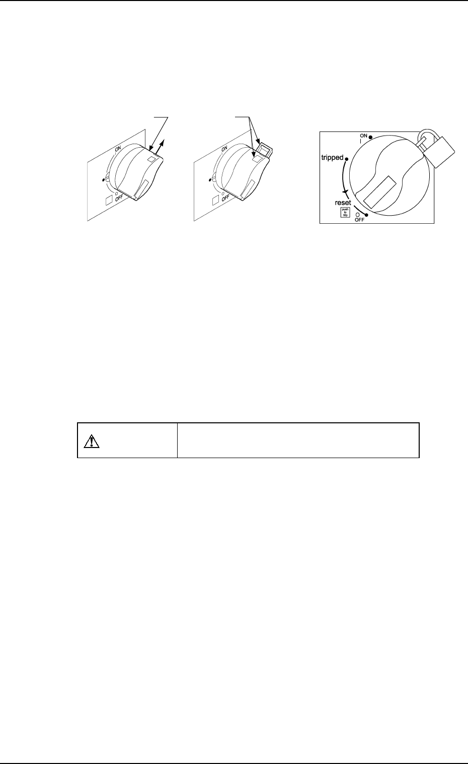
• Padlocking
(1) Pull out the power breaker lock lever in the direction shown by Arrow A
in Fig. 1.7-1. (Do not take your hand off the crank).
(2) Padlock the lock hole. (See Fig. 1.8)
Note: There are two types of padlock for the power breaker (No. 2500
30 MM) and for main valve (No. 2500 25MM). Use correct one.
• Unlocking the Crank (Canceling the Lock Mode of the Power Breaker Crank)
(1) Disengage the shackle of the padlock and detach it from the main power
breaker. See Fig. 1.8.
Only the personnel in charge of maintenance should disengage the shackle
of the padlock to unlock the main power breaker.
CAUTION
Designate a personnel who can have charge of
the padlock key.
Fig. 1.7-1
Fig. 1.8 Padlocked
Lock Lever
5. Operation Panel (Names and Functions)
9910-001 1-30 Tg0246-PM-OP
A
Lock Slot
Fig. 1.7 Before Padlocking
Fig. 1.7-2
5. Operation Panel (Names and Functions)
0304-002 1-31 Tg0246-PM-OP
Fig. 1.10
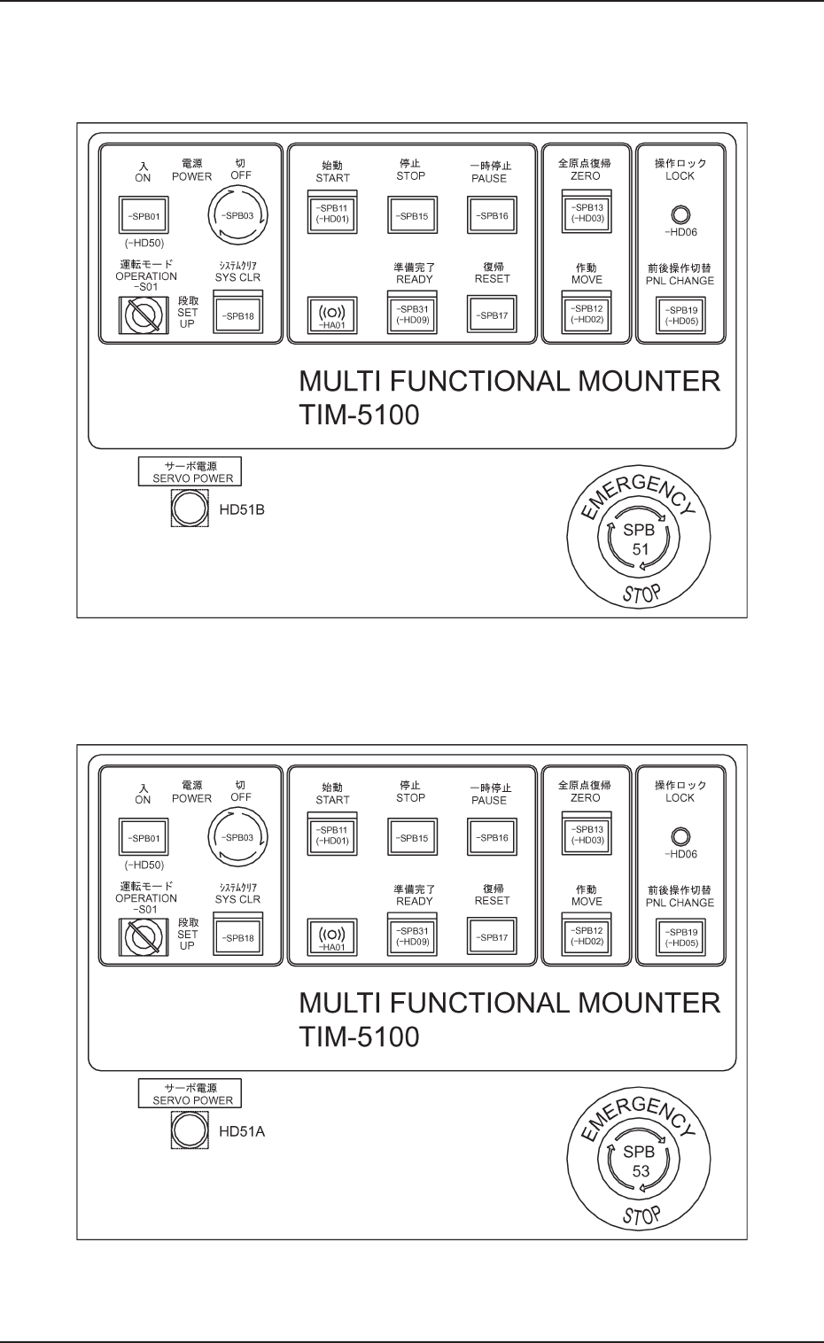
5.2 Front and Rear Operation Panels
Front Panel
Rear Panel
Fig. 1.9
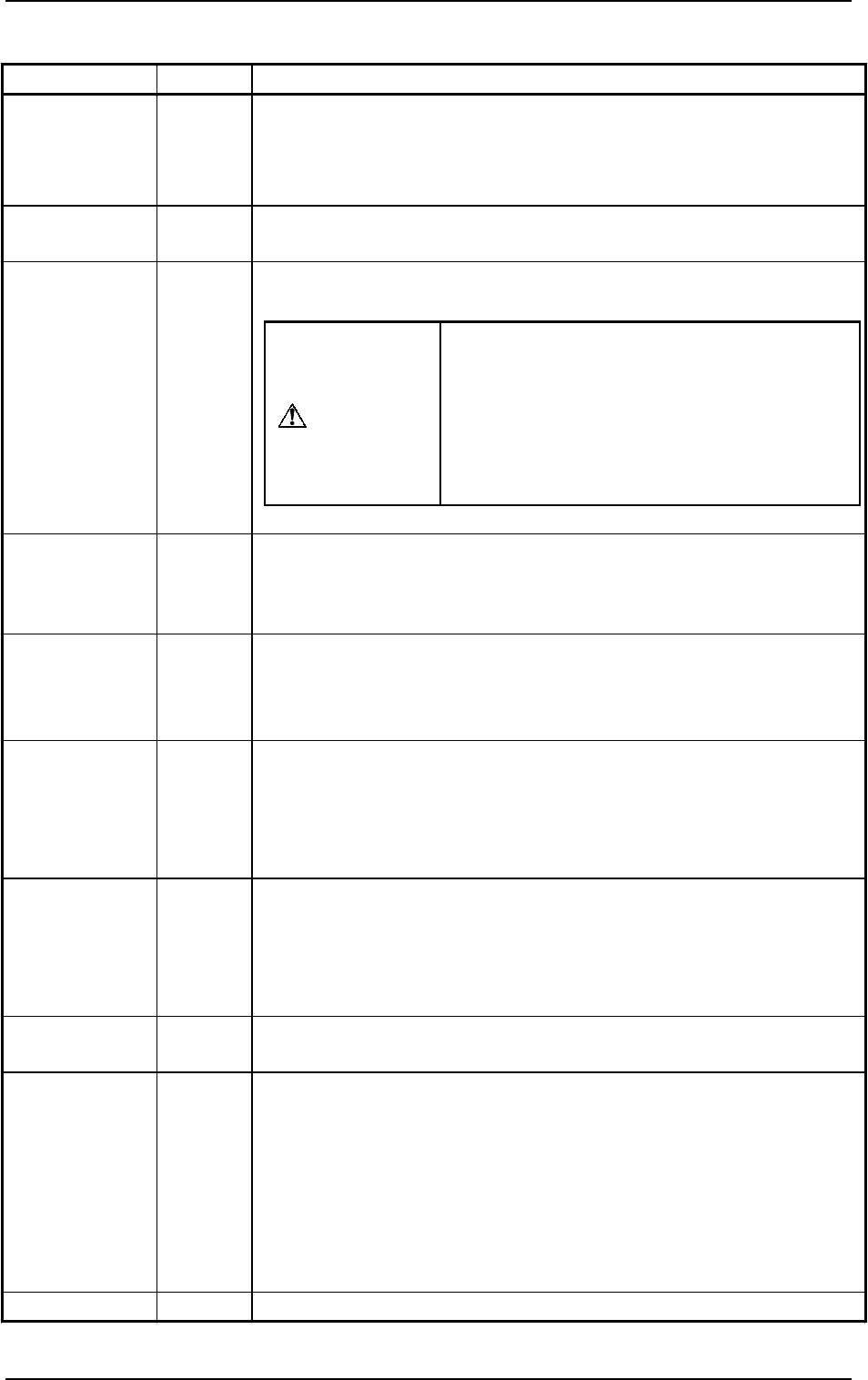
Switch Name
Symbol Function
POWER ON -SPB01
(-HD50)
•
Supplies the power for operation.
The red LED illuminates when only power for operation is supplied.
The green LED illuminates when power for both operation and loads is
supplied.
POWER OFF -SPB03
• Turns off the power for operation.
Turning the lock type switch clockwise shuts off the power.
OPERATION
SET UP
-S01
•
Changes over the switch from “OPERATION” to “SET UP” or vice
versa.
•
SYS CLR -SPB18
•
Clears the system to the initial setting or cancels an operation.
Note: When the [SYS CLR] button is pressed at the [OPERATION/SET
UP] switch set to the “SET UP” side, the system cannot be
cleared.
START -SPB11
(-HD01)
•
Starts automatic operation of the machine.
While the LED is ON, it indicates that the machine is running
automatically.
It extinguishes when the machine is stopped during operation.
STOP -SPB15
• Stops automatic operation of the machine.
It is possible to stop the automatic operation with this switch during
the X/Y beam test.
• When this button is pressed during zeroing operation, each individual
devices are stopped.
PAUSE -SPB16
• Stops automatic operation temporarily.
It is possible to temporarily stop the automatic operation with this
switch during the X/Y beam test.
• When this button is pressed during zeroing operation, each individual
devices are stopped temporarily.
RESET -SPB17
• Releases an error signal and resumes the power (Power ON) for the
servomotor driver.
READY -SPB31
(-HD09)
Front Operation Panel
This button is used to tell the machine that the feeders such as tape and
stick feeders on the front side (Side B) are ready for replacement.
• Refer to “5.5 [READY] Button of Section 1” for details.
Rear Operation Panel
• This button is used to tell the machine that the feeders such as tape and
stick feeders on the rear side (Side A) are ready for replacement.
• Refer to “5.5 [READY] Button of Section 1” for details.
BUZZER -HA01
• Sounds when an error occurs.
When the switch is changed to “SET UP”,
the interlock functions of the safety door,
etc., are deactivated.
Do not set this switch to “SET UP” except
for a set-up operation.
Refer to “1.2 [OPERATION/SET UP]
Switch of Section 2” for details.
WARNING
Table 1.2-1
9910-001 1-32 Tg0246-PM-OP
5. Operation Panel (Names and Functions)