1OM-1064-002.pdf - 第147页
6. Starting, Emergency Stop, and T emporary Stop (Pause) Operations for Automatic Operation (“PLACE” Mode) 6. Starting, Emergency Stop, and T emporary Stop (Pause) Operations for Automatic Operation (“PLACE” Mode) 6.1 Ge…

5. Preparation and Confirmation before Operation
5.3.3 Confirmation of Components
(1) Verification of Component Library Data
A component recognition test must be performed to verify that the cre-
ated component library data is normal.
Refer to “7.2 COMPONENT RECOG. TEST Display of Section 3 in
Volume 4” for details.
(2) Confirmation of Pick-Up Position
If the component pick-up position deviates greatly from the center of the
nozzle, it will cause a pick-up error. To avoid such an error, the compo-
nent pick-up position must be taught in the following cases.
• When the center of the picked component deviates from the center of
the nozzle, perform the teaching operation (teaching operation for pick-
up position) on the feeder (B) offset data.
• When the component has a limited surface to be picked up or cannot
be picked up because it has a hole or a protrusion at its center, use the
[TEACH ECC. PICKUP POS [PICKUP LOC. ADJ] key to perform
the teaching operation on the eccentric pick-up position.
CAUTION
Only an well-trained personnel shall perform
teaching operations.
Otherwise, the pick-up rate may deteriorate be-
cause teaching operations are performed to ad-
ditionally modify the component library data and
the pattern program data.
Refer to “6.9 PICK-UP LOCATION Display of Section 3 in Volume 4”
for details.
5.3.4 Placement Verification
Place actual components on a P.C.B. and verify that the component can be
placed without any hindrance.
Refer to “6. Starting, Emergency Stop, and Temporary Stop (Pause) Opera-
tions for Automatic Operation (“PLACE” Mode) of Section 2” for the proce-
dures.
5.4 Setting of Operation Mode
Follow Steps (1) through (4) below before starting the automatic operation
(“PLACE” Mode).
(1) Automatic Feeder Axis Adjustment Mode
Refer to “5.1 AUTOMATIC FEEDER AXIS ADJUSTMENT MODE
Display of Section 3” for details.
(2) Overall Tact-Time Reduction
Refer to “5.2 OVERALL TACT-TIME REDUCTION Display of Sec-
tion 3” for details.
(3) Recognition Monitor Display Mode
Refer to “5.3 RECOG MONITOR DISPLAY MODE Display of Section
3 ” for details.
(4) P.E.C. Manual Alignment Mode
Refer to “5.4 P.E.C. MANUAL ALIGNMENT MODE Display of Sec-
tion 3” for details.
0004-002 2-48 Tg0246-PM-OP

6. Starting, Emergency Stop, and Temporary Stop (Pause) Operations for Automatic Operation (“PLACE” Mode)
6. Starting, Emergency Stop, and Temporary Stop
(Pause) Operations for Automatic Operation
(“PLACE” Mode)
6.1 General Start Procedure
(1) Perform the following operations.
• Preparation of Pattern Program
(Refer to “5.1 Preparation of Pattern Program of Section 2” for details)
• Refer to “5.2 Program Change Operation of Section 2 ” for details.
• Pattern Program Checking for Production Model
(Refer to “5.3 Pattern Program Checking for Production Model of Sec-
tion 2” for details)
“PLACE” must be set in the “PLACEMENT MODE” data box at the
“OPERATION DATA” display in the pattern program.
(The LED of the [PASS/PLACE CHANGE] key at the “AUTO OPN.
SUB-MENU” display illuminates green.)
• Refer to “5.4 Setting of Operation Mode of Section 2” for details.
(2) Confirm that the maintenance covers (maintenance covers, supply
covers, safety bars) are closed.
(3) Set the [OPERATION/SET UP] switch to the “OPERATION” side and
remove the selection key from the machine.
(4) Confirm that the LEDs (-HD09) of the [READY] button on the front and
rear operation panels are “ON”.
Press the [READY] button to turn it on if necessary.
To set the opposite side ready for operation, select the [SIDE A] or the
[SIDE B] key (Only the opposite side can be selected. Press the [READY]
button in the case of the operation panel.) under the label “(FEEDER
CHANGE-OVER PREPARATION COMPLETE)” at the “AUTO OPN
SUB-MENU” display and press the [MOVE] button. (Hierarchical Se-
quence: “AUTO OPN. MODE (PLACEMENT)” Display → “AUTO
OPN. SUB-MENU” Display)
(5) Check the surroundings of the machine and confirm safety before start-
ing the automatic operation.
CAUTION
Check carefully that there is no person around
the moving mechanisms of the machine.
(Especially, the other side of machine opera-
tion)
Make sure that no objects remain within the
moving mechanisms of the machine.
(Tools and Parts)
0004-002 2-49 Tg0246-PM-OP
6. Starting, Emergency Stop, and Temporary Stop (Pause) Operations for Automatic Operation (“PLACE” Mode)
(6) Open the “AUTO OPN. MODE <PLACEMENT>” display and check
the origin marks “”.
Note: When “” marks do not appear before the devices other than
“INPUT MACHINE”, the automatic operation cannot be started.
• When “” marks appear before the devices other than “INPUT MA-
CHINE”, proceed to Step (8).
• When “” marks do not appear before some devices other than “IN-
PUT MACHINE”, proceed to Step (7).
(7) Press the [ZERO] button.
• The “” marks appear before all devices except for “INPUT MA-
CHINE”.
(8) Press the [START] button.
• Work requirement and ready signals are sent to the input machine side.
• When the input machine is set ready for operation, it receives the work
requirement signal from the main machine and right after that, P.C.B.’s
start flowing into the input machine and the automatic operation (place-
ment operation) starts.
When the input machine is not set ready, the machine is set in the
“WAIT” mode.
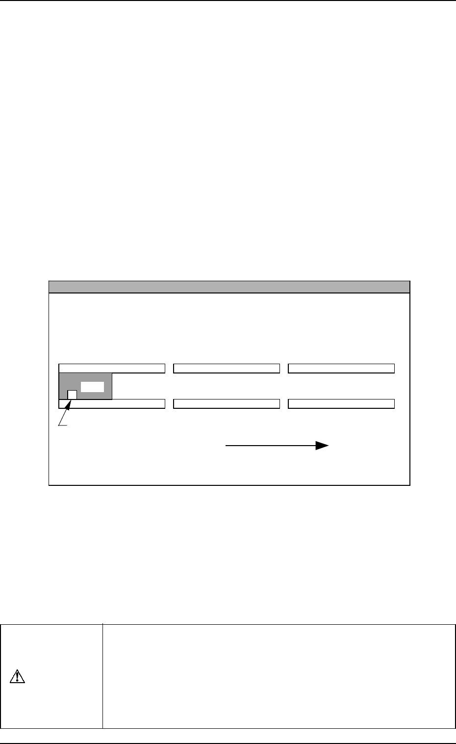
Reference
z
When the machine is operated singly (isolated operation such as an actual component
placement test), a P.C.B. must be put on the input conveyor as shown in the figure
such that the P.C.B. detection sensor is turned ON.
L Conveyer P.C.B. Detection L Sensor (-BPH141)
L Conveyor
(Input Conveyor)
R Conveyor
(Output Conveyor)
P.C.B. Flow Direction
P.C.B.
P Conveyor
(P.C.B. Positioning Section)
The figure shows that a P.C.B. is transferred from left to right when viewed from the
front side of the machine.
• When the automatic operation (component placement operation)
starts, all “” marks (origin marks) disappear and the LED (-HD01)
of the [START] button and the tower light (green) illuminate.
Notes: (a) The machine cannot be started unless the “AUTO OPN.
MODE <PLACEMENT>” display is active.
(b) When a P.C.B. already exists in the P.C.B. positioning sec-
tion, the machine does not place any components on the
P.C.B. and discharges the P.C.B.
CAUTION
To stop the machine immediately in an emergency, press one of the
[EMERGENCY STOP] buttons.
Refer to “6.8.3 Emergency Stop Procedure of Section 2” for details.
Refer to “6.7.2 Reset and Start Procedure from Emergency Stop of
Section 2” for details on how to reset the machine from emergency
stop.
9910-001 2-50 Tg0246-PM-OP