1OM-1064-002.pdf - 第134页
5. Preparation and Confirmation before Operation Movable Chute Fixed Chute P .C.B. Positioning Section (P Conveyor) 5.2.2 Adjustment of P .C.B. Positioning Section 5.2.2.1 Adjustment of Conveyor Width (1) Use the automat…

5. Preparation and Confirmation before Operation
(10) When the [CHANGE CURRENT PRGM.] key is pressed, only the data
for the current pattern program is set.
Note: When an error is detected during set-up operation such as the
automatic conveyor width adjustment, the machine does not per-
form the program change operation.
Remove the cause of the error and perform the program change
operation again.
9910-001 2-35 Tg0246-PM-OP
5. Preparation and Confirmation before Operation
Movable Chute
Fixed Chute
P.C.B. Positioning Section (P Conveyor)
5.2.2 Adjustment of P.C.B. Positioning Section
5.2.2.1 Adjustment of Conveyor Width
(1) Use the automatic set-up function to adjust Dimension A to “P.C.B.
Width + 0.5 mm (standard value)”.
In an actual case, the parameter set in the “CLEARANCE”data box
is used.
(2) Transfer P.C.B.’s through manual operation and check that they can
be conveyed smoothly without falling off.
0004-002 2-36 Tg0246-PM-OP
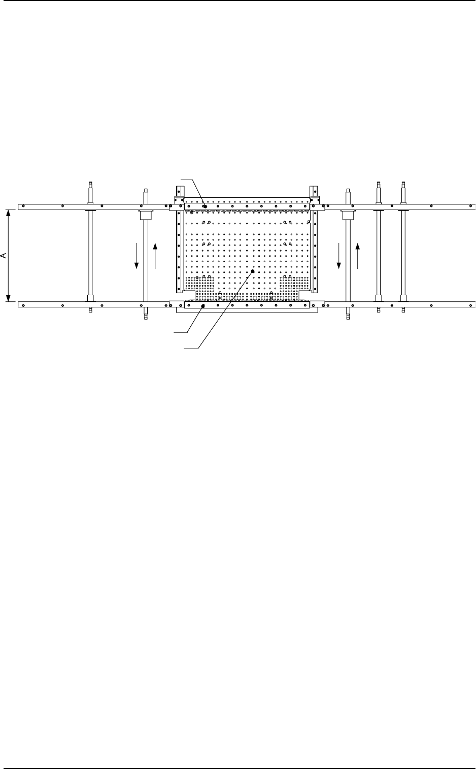
Fig. 2.23 View based on Reference Point "R-FRONT"
Notes: (a) Pay attention to the following points when the conveyor width
is automatically set up.
• When the conveyor width is zeroed, it is adjusted to “381 mm
(the largest P.C.B. size)”. Check that nothing around the con-
veyor touches part of the conveyor.
• Confirm that there is no P.C.B. on the conveyor.
Before the conveyor width set-up operation is initiated, each
conveyor is automatically activated to check that no P.C.B. is
located at any irregular position.
• Confirm that the P.C.B. support pins are removed.
(b) Fig. 2.23 shows the view based on Reference Point “R-FRONT”.
The same procedure applies regardless of a reference point.
5. Preparation and Confirmation before Operation
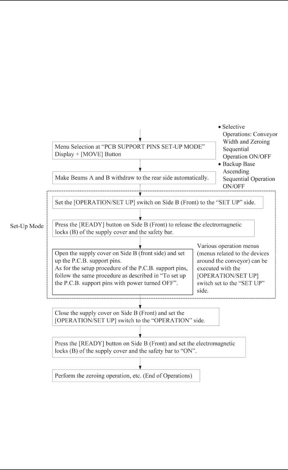
5.2.2.2 Setting Procedure of P.C.B. Support Pins
To set up the P.C.B. support pins at the “PCB SUPPORT PINS
SET-UP MODE” display
• Refer to “10. P.C.B. Support Pins Set-Up Mode of Section 4” for
details.
Starting Condition: • All devices must be zeroed.
• The maintenance/supply cover must be
closed.
• The LED of the [READY] button must be
“ON” (power supplied to the beam)
0004-002 2-37 Tg0246-PM-OP