1OM-1064-002.pdf - 第242页
*8 *9 *7 *1 *2 *3 *4 *5 *6 10. P .C.B. Support Pins Set-Up Mode When the [PCB SUPPOR T PINS SET-UP MODE] key is pressed at the “MANUAL MODE” display , the following display appears on the screen. This display enables the…

(3) Select the key in the head section for the backup memory condition to be
corrected. Then, choose the [NOZ. SET (OV. WR.)] or the [NOZ. RE-
SET (DELETE)] key and press the [SET] key.
(4) After all head condition is rewritten completely, press the [RTN] key.
The “DATA SAVE MODE” display appears on the screen, asking whether
or not the corrected data should be saved.
(5) Verify the rewritten contents and compare them with the actual condi-
tion.
(6) Select the [SAVE] or the [DON'T SAVE] key.
When either one of the keys is selected, the “MANUAL NOZZLE
CHANGE OPERATION” display resumes with the information in the
backup memory being updated.
9. Manual Nozzle Change Operation
9910-001 4-25 Tg0246-PM-OP
*8
*9
*7
*1
*2
*3
*4
*5
*6
10. P.C.B. Support Pins Set-Up Mode
When the [PCB SUPPORT PINS SET-UP MODE] key is pressed at the
“MANUAL MODE” display, the following display appears on the screen.
This display enables the setting of the environmental condition required to
specify the position of the P.C.B. support pins.
Refer to “5.2.2 Adjustment of P.C.B. Positioning Section of Section 2” for the
procedure to specify the position of the P.C.B. support pins.
0004-002 4-26 Tg0246-PM-OP
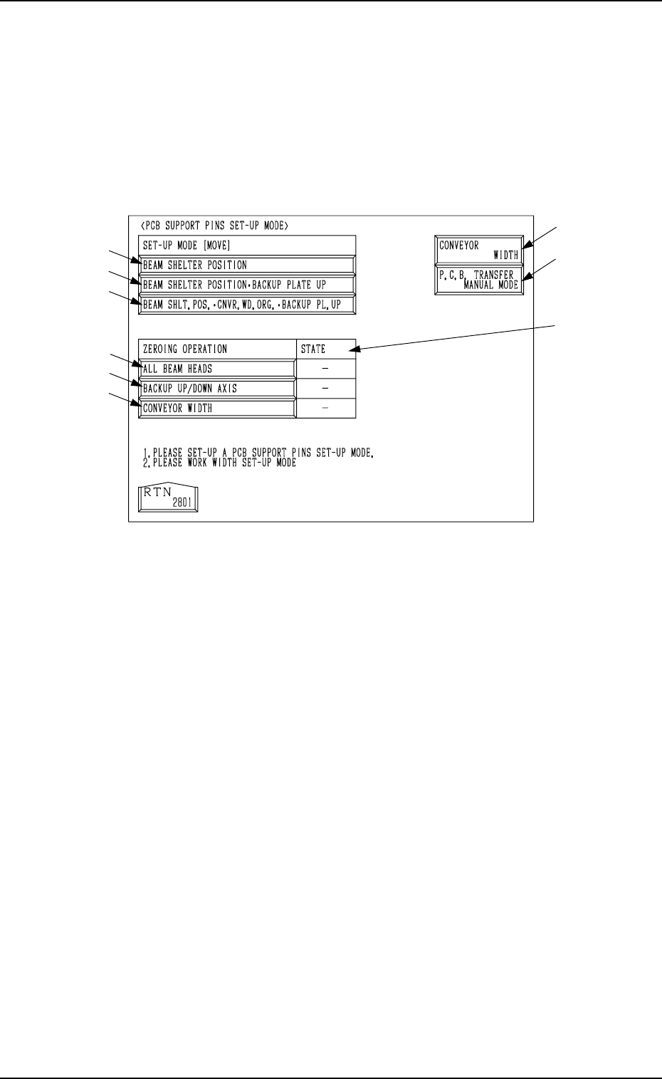
10. P.C.B. Support Pins Set-Up Mode
Fig. 4.14
*1 [BEAM SHELTER POSITION] Key
When this key is selected and the [MOVE] button is pressed, both beams A
and B retreat to the rear side (Side A).
*2 [BEAM SHELTER POSITION
•
BACKUP PLATE UP] Key
When this key is selected and the [MOVE] button is pressed, both beams A
and B retreat to the rear side (Side A) and the backup plate (base) moves
up.
*3 [BEAM SHLT. POS. CNVR. WD. ORG.
•
BACKUP PL. UP] Key
When this key is selected and the [MOVE] button is pressed, both beams A
and B retreat to the rear side (Side A), the conveyor widens (opens) to the
origin position, and the backup plate moves up.
Ref.: Before the conveyor width set-up operation is initiated, each con-
veyor is automatically activated to check that no P.C.B. is located at
any irregular position.
*4 [ALL BEAM HEADS] Key
When this key is selected and the [MOVE] button is pressed, both beams A
and B are zeroed.
*5 [BACKUP UP/DOWN AXIS] Key
When this key is selected and the [MOVE] button is pressed, the backup
plate is zeroed.

*6 [CONVEYOR WIDTH] Key
When this key is selected and the [MOVE] button is pressed, the conveyor
width is zeroed.
Ref.: Before the conveyor width set-up operation is initiated, each con-
veyor is automatically activated to check that no P.C.B. is located at
any irregular position.
*7 STATE
“” : Zeroed
“ ” : The current position is managed.
“
” : The current position is indefinite.
*8 [CONVEYOR WIDTH] Key
When this key is pressed, the “CONVEYOR WIDTH” display (one of the
product change menus) appears on the screen.
Refer to “4.2 Manual Set-Up at Each Display (Display for Each Device) of
Section 4” for details.
*9 [P.C.B. TRANSFER MANUAL MODE] Key
When this key is pressed, the “MANUAL TRANSFER OPERATION” dis-
play appears on the screen.
Refer to “8. Manual Transfer Operation of Section 4” for details.
9910-001 4-27 Tg0246-PM-OP
10. P.C.B. Support Pins Set-Up Mode