1OM-1064-002.pdf - 第50页
41. Standard Accessory Parts List 2. Specifications 0004-002 1-20 Tg0246-PM-OP No . Name Part N o. Part N ame Q'ty Remarks 1 M a s t e r J i g 630 040 4715 AS S Y , F R A M E 1 • For Confirmation of Component Pick -…
40. Requirements for Simultaneous Component Picks
(1) Feeders Available for Simultaneous Component Picks
Tape Feeders
(2) Requirements for Simultaneous Picks
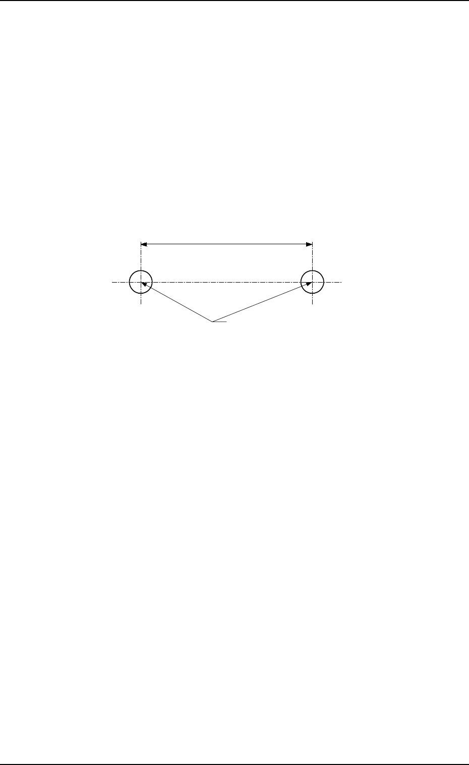
As the distance between the nozzle rotational centers of Heads
#1 and #2 is “108 mm”, components can be picked up simulta-
neously only when the distance of the component supply posi-
tion is “108 mm”.
Consult our sales personnel for details.
Notes: (a) When two components are on different feeder
bases, they cannot be picked up simultaneously.
(b) When a component is specified for eccentric pick-
up operation, it cannot be picked up simultaneously.
Simultaneous Pick Position
(Component Loading Position)
108
9910-001 1-19 Tg0246-PM-OP
2. Specifications
Unit : mm

41. Standard Accessory Parts List
2. Specifications
0004-002 1-20 Tg0246-PM-OP
No. Name Part No. Part Name Q'ty Remarks
1 Master Jig 630 040 4715 ASSY, FRAME 1 • For Confirmation of
Component Pick-Up
Position and Level, etc
2 PCB Backup Pin 630 075 8481 PIN, LOCATE 20 • For PCB Supporting
3-1 Vacuum Nozzle
(MA04)
630 075 9334 ASSY, NOZZLE 2 • For Component Pick
3-2 Vacuum Nozzle
(MA05)
630 075 9341 ASSY, NOZZLE 2 • For Component Pick
3-3 Vacuum Nozzle
(MA06)
630 075 9358 ASSY, NOZZLE 2 • For Component Pick
3-4 Vacuum Nozzle
(MF01)
630 075 9365 ASSY, NOZZLE 2 • For Component Pick
4 Vacuum Filter 630 069 5816 AIR LINE EQPT 80 • Spare for Dust
Removal
5 Jig for Component
Recognition Offset
630 073 0036 PLATE 1 • For Offset Teaching
(JG-0085)
6 Vacuum Filter
Replacement Jig
630 076 6691 TOOL, HAND 1 • For Vacuum Filter
Replacement
7 Empty Tape Box 630 075 2120 BOX 2 • For Empty Tape
Collection
8-1 Padlock 630 054 9676 MECH PARTS
No. 2500 30 MM
1 • To lock the power
breaker
8-2 Padlock 630 053 4917 MECH PARTS
No. 2500 25 MM
1 • To lock the main
valve of the air source
9-1 Lamp 630 000 1983 LAMP 30V 10W 2 • Spare for Light Tower
9-2 Lamp 630 075 3325 LAMP 24V 10W 2 • Spare for Component
Shortage Indicator
9-3 Lamp 630 005 5580 LAMP 2 • Spare for P.E.C.
Recognition Lighting
10-1 Fuse 423 025 2000 FUSE 250V 0.4A 2 • Spare for F201, F202,
F203, and K99
10-2 Fuse 423 022 8203 FUSE 250V 3.15A 2 • Spare for F100, F101,
F113,and F030
10-3 Fuse 423 025 1904 FUSE 250V 1.6A 2 • Spare for F102
10-4 Fuse 423 022 8005 FUSE 250V 1A 2 • Spare for F105 to F110,
F121 to F125, F152A,
F152B, F153A, F153B,
and F351A
10-5 Fuse 423 022 8104 FUSE 250V 2A 2 • Spare for F111 and
F112
10-6 Fuse 423 025 5100 FUSE 250V 4A 2 • Spare for F011 and
F021
10-7 Fuse 423 022 8302 FUSE 250V 5A 2 • Spare for F114,
F131 to F133,
F151, F161, F001,
F006, F012, and F022
10-8 Fuse 423 025 2109 FUSE 250V 6.3A 2 • Spare for F002 to
F005
10-9 Fuse 423 027 3500 FUSE 250V 0.315A 2 • Spare for F051A and
F051B
10-10 Fuse 423 022 8500 FUSE 250V 10A 2 • Spare for Recognition
Lighting Control
Board
3. Functions
9910-001 1-21 Tg0246-PM-OP
3. Functions
3.1 Component Recognition Function
In the component recognition system, an image of the picked component is cap-
tured by the component recognition camera, image-processed, and recognized
by the recognition device. The deviation from the specified pick-up position is
corrected based on the results of the recognition for accurate component place-
ment.
The machine is basically designed to recognize all components and correct the
positional deviations for accurate component placement.
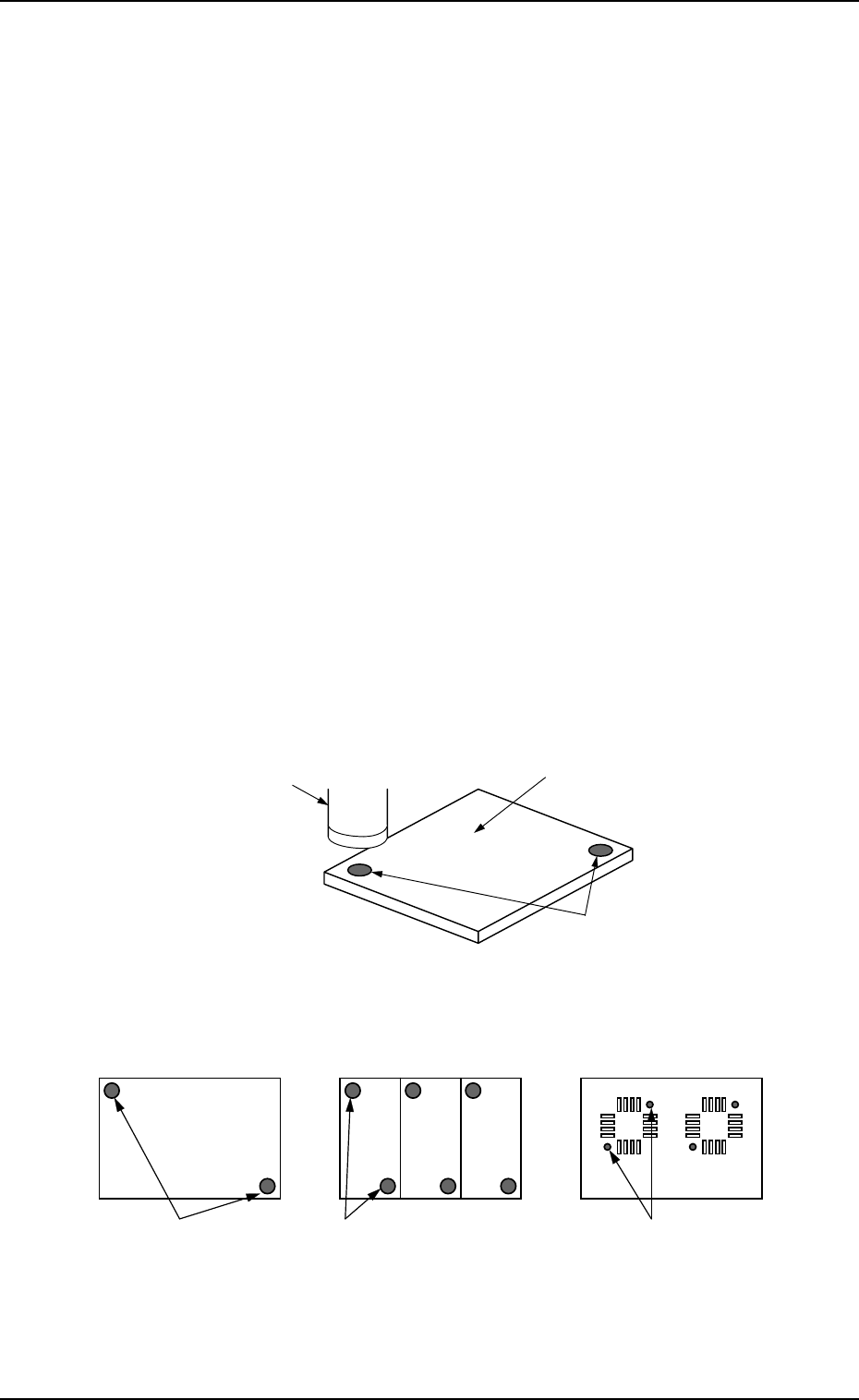
3.2 P.E.C. Recognition Function
An image of the fiducial mark on the P.C.B. is captured by the P.E.C. camera,
image-processed, and recognized by the recognition device. The positional de-
viation of the positioned P.C.B. is corrected based on the results of the recogni-
tion.
• Global P.E.C. Recognition: The whole area of a P.C.B. is recognized to glo-
bally correct the positional deviations.
• Image P.E.C. Recognition: Fiducial marks are put on each unit P.C.B. of a
multi-unit P.C.B. and recognized to correct the positional deviation of each
unit P.C.B.
• Local P.E.C. Recognition: Fiducial marks are put for each individual compo-
nent placement points and recognized to correct the positional deviation of
each point on the P.C.B.
Fig. 1.1
Fig. 1.2
P.C.B.
Recognition Camera
Fiducial Marks
Local P.E.C. Recognition
Image P.E.C. Recognition
(Multi-Unit P.C.B.)
Global P.E.C. Recognition
Fiducial Marks
Fiducial MarksFiducial Marks
Refer to “2.3.2 Operation Data (P.E.C. Recognition) of Section 2 in Volume 2”
for details.