1OM-1064-002.pdf - 第43页
[Measuring Condition] • Measuring Posi tion Position 1 m away and 1.6 m in height from the machine. • Noise Measuring Instrument Model: RI ON NA-60 (Range A) • Requirements for Ope r ation Test Run Actions : No P.C.B. Tr…
9910-001 1-12 Tg0246-PM-OP
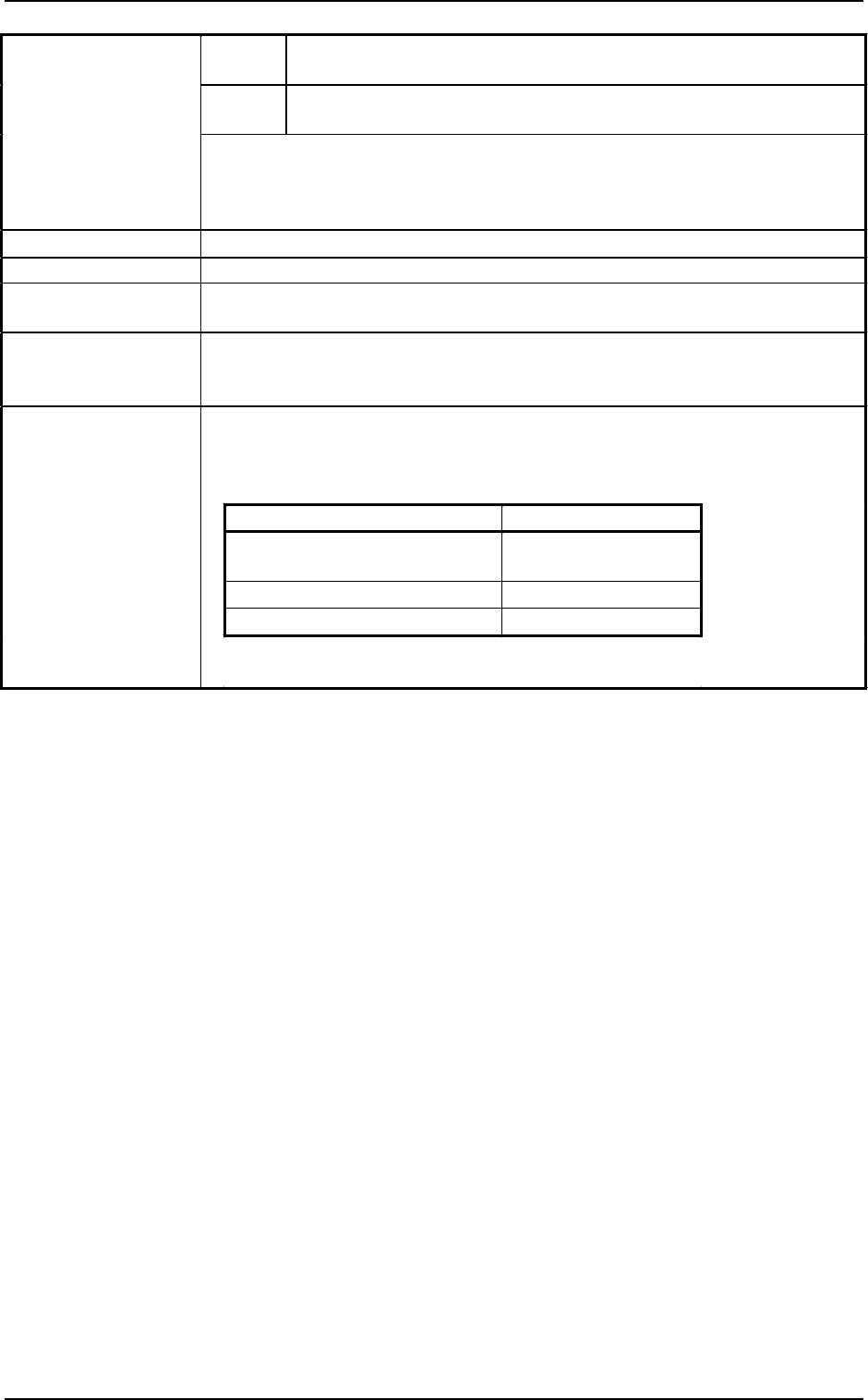
2. Specifications
Supply
Pressure
0. 49 to 0.69 MPa (5 to 7 kgf/cm
2
)
Dry and Clean Air (Moisture, oil, and dust are removed.)
Set
Pressure
0.49 MPa (5 kgf/cm
2
)
31. Air Supply
• Dray and Clean Air
Moisture : Dew Point −17℃ or lower (Atmospheric Pressure)
Oil : 0.1 mg/m
3
or less (ANR)
Dust : Solid Material 0.01 µm or less
32. Air Consumption Approx. 20 l/min (ANR)
33. Vacuum Pressure −93 kPa (70 cmHg)
34. Environmental
Condition
Temperature : 20 ± 10°C
Humidity : 30 to 80% (Avoid dew condensation.)
35. Basic Dimensions 1,700 (width) × 2,228 (depth, excluding the safety bar) × 1,565 mm (height)
Notes : (a) The height becomes 2,100 mm when the light tower is included.
(b) The depth becomes 3,118 mm when the safety bar is included.
2,420 kg (only the main body section)
Note : The mass changes depending on the type of feeders to be installed.
Mass of Options (For Reference)
Name Mass (kg)
Tape Feeder The mass depends on
feeder types.
Stick Feeder (Vibratory) Approx. 6.5/feeder
Multi-Layer Tray Feeder Approx. 180/feeder
Note : The mass related to components is not included.
36. Basic Mass
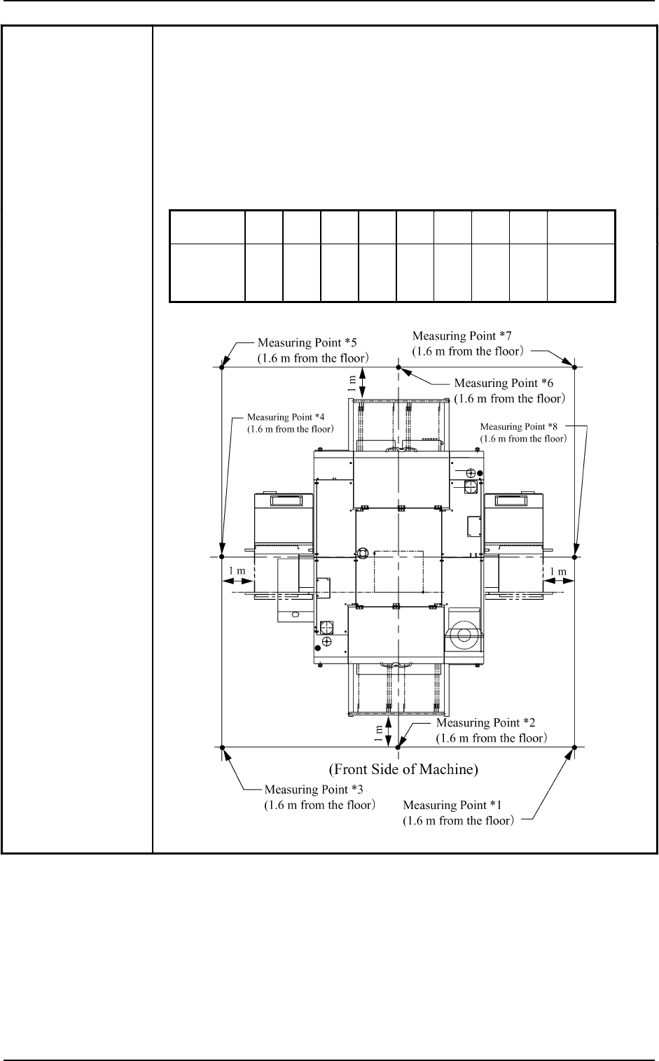
[Measuring Condition]
• Measuring Position
Position 1 m away and 1.6 m in height from the machine.
• Noise Measuring Instrument
Model: RION NA-60 (Range A)
• Requirements for Operation
Test Run Actions: No P.C.B. Transfer, No Component Picks/No
Recognition/No Placement, Repetition of Stages 11 and 12 for Multi-Layer
Tray Feeders L/R, Only One 32 mm Tape Feeder Activated (FDR No. 228)
Measuring
Point
*1 *2 *3 *4 *5 *6 *7 *8
Remarks
Measured
Noise
Value
[
dB
]
70.8 70.6 70.8 68.4 68.7 69.6 68.4 69.1
Background
Noise
(Surroundings)
48.7 [dB]
37. Measured Noise
Value
2. Specifications
9910-001 1-13 Tg0246-PM-OP
2. Specifications
9910-001 1-14 Tg0246-PM-OP
38. Conditions for
Component
Placement
(1) Shape of Vacuum Nozzle
When components are to be placed to the previously-placed components or
the obstacles, the shape of the vacuum nozzle becomes part of the
constraint condition. Refer to “8. Vacuum Nozzles of Section 1 ” for the shapes
of vacuum nozzles.
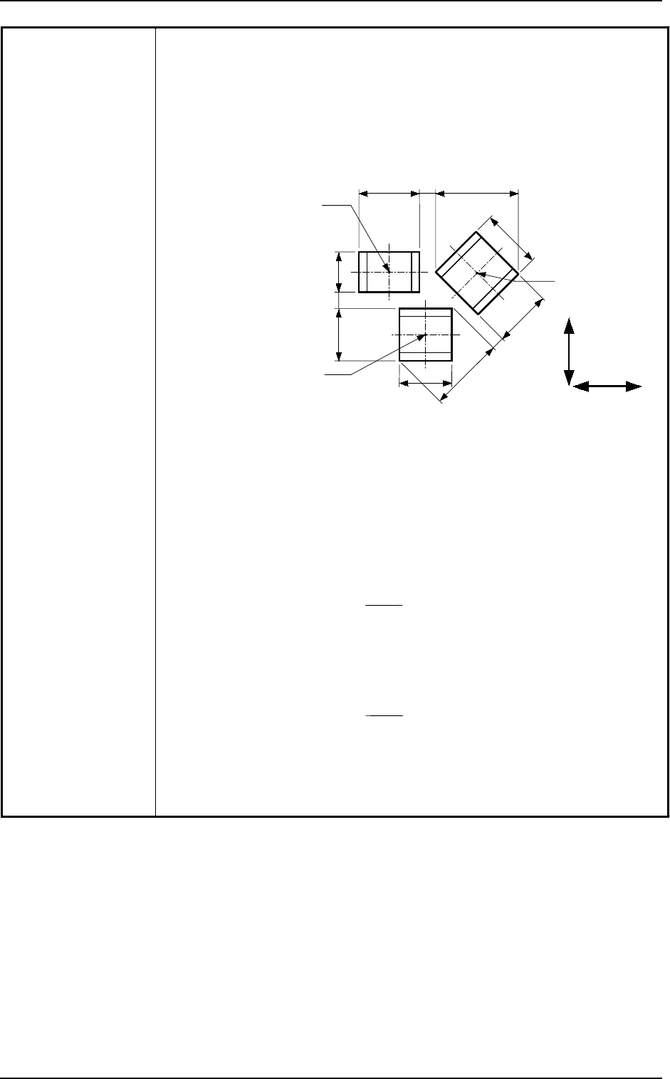
(2) Adjoining Distances between Components
(when the component placement position is taken into consideration)
A
a
G
F
E
b
B
C
c
H
Component
Placement Point 3
Component
Placement Point 2
Component
Placement Point 1
X Direction
Y Direction
Note: (a) The above figure shows that the vacuum nozzles are not protruding
from the outer shapes of components. Consult our sales personnel
for details.
(b) “A to H” in the above figure show the maximum dimensions including
the variations in the dimensions of each component. The minimum
adjoining distances (a, b, and c) of each component should be 0.4 mm.
(c) The minimum adjoining placement position data for component
placement points 1 and 3 is
“X Direction Data = + Min. 0.4 mm”
(The Y direction data is not related.)
(d) The minimum adjoining placement position data for component
placement points 1 and 2 is
“Y Direction Data = + Min. 0.4 mm”
(The X direction data is not related.)
(e) See the above figure and obtain the minimum adjoining placement
position data for component placement points 2 and 3.
B + E
2
A + G
2