1OM-1064-002.pdf - 第205页
6. RECOVERY OPN. TEACHING OPN. Display Fig. 3.20 * 1 Move the line cursor (blue), using the key *2 or *3. * 2 [ ] Key Press this key to move the line cursor upward. When the line cursor is located at the top and this key…
6. RECOVERY OPN. TEACHING OPN. Display
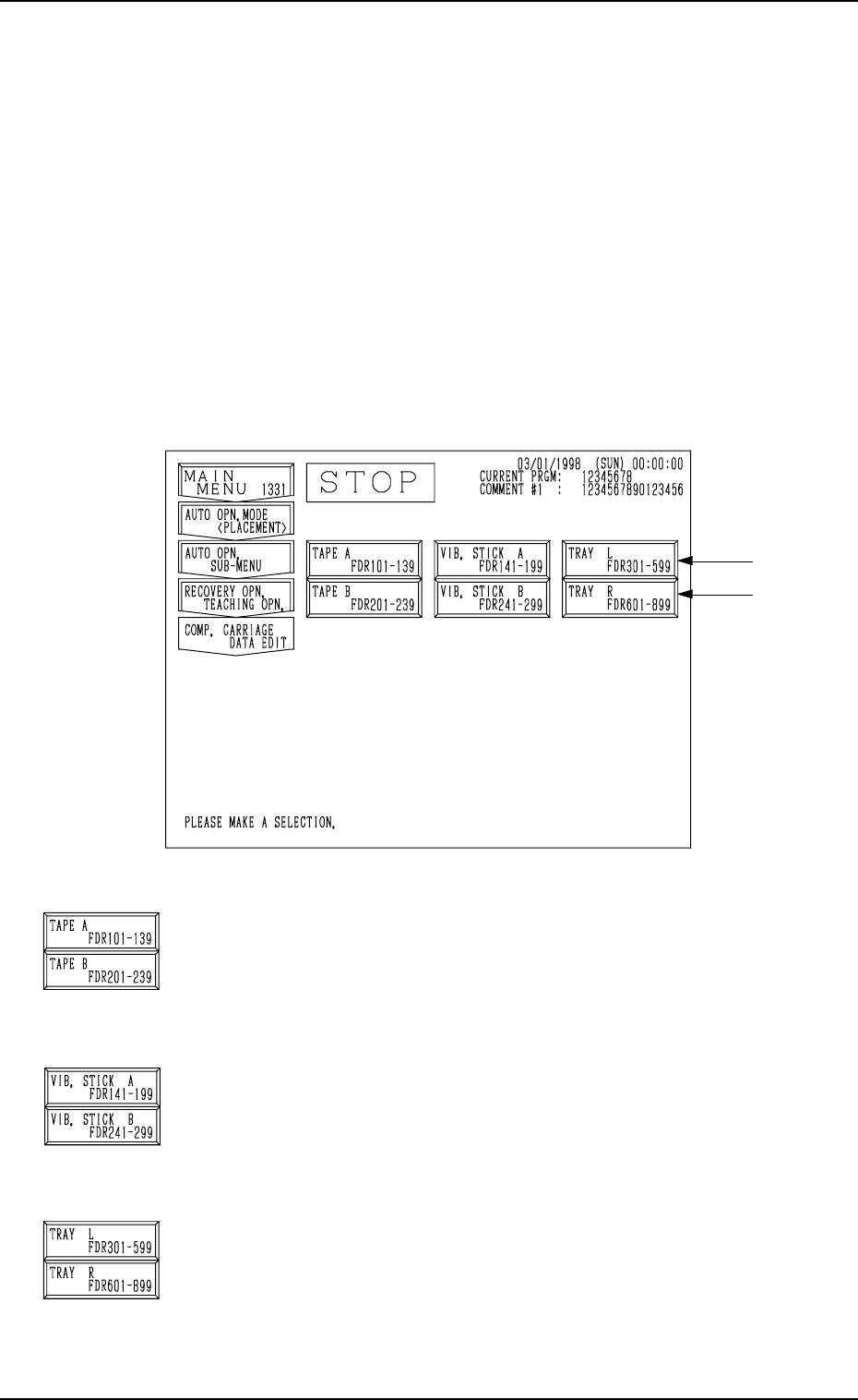
Fig. 3.19
[TAPE A FDR101-139] and [TAPE B FDR201-239] Keys
When either one of these keys is pressed, the corresponding
“COMPONENT CARRIAGE DATA EDIT” display appears
on the screen, enabling you to change the component car-
riage data related to the tape feeders.
[VIB. STICK A FDR141-199] and [VIB. STICK B FDR241-
299] Keys
When either one of these keys is pressed, the corresponding
display appears on the screen, enabling you to change the
component carriage data related to the vibratory stick feeders.
[TRAY L FDR301-599] and [TRAY R FDR601-899] Keys
(Option)
When either one of these keys is pressed, the corresponding
display appears on the screen, enabling you to change the
component carriage data related to the multi-layer tray feeders.
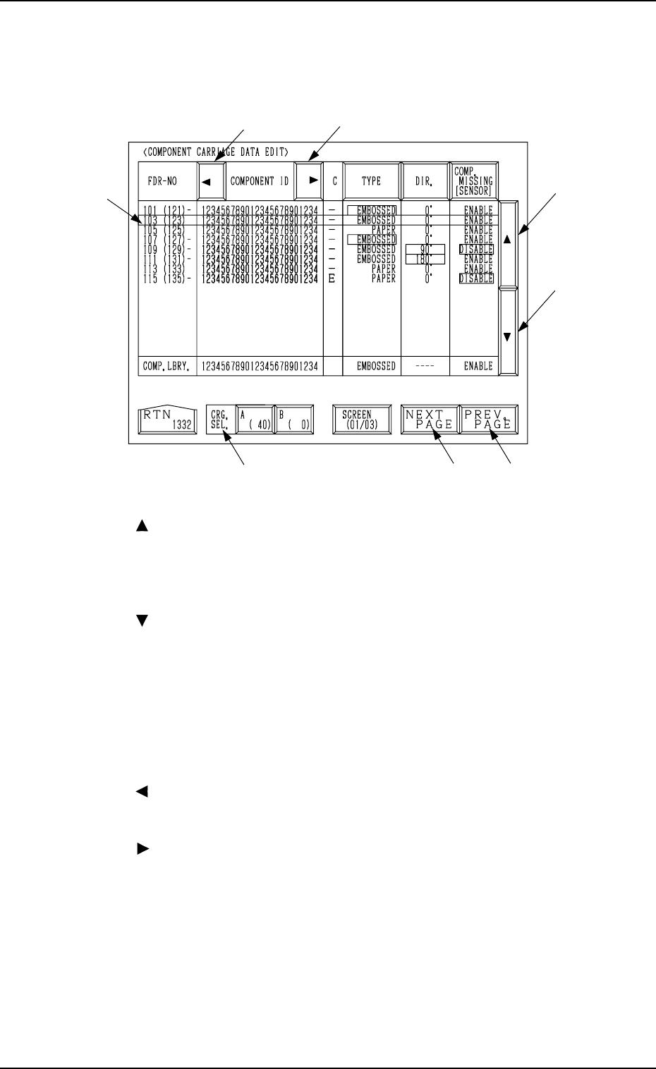
6.3 COMP. CARRIAGE DATA EDIT Display (Simplified
Packaging Direction Change Function)
• When components are supplied after component shortage during automatic
operation and the packaged posture of the supplied components differs from
that of the components being used so far due to unavailability, etc., this
function is used to temporarily change the packaged posture.
Note: Only the limited data for the packaged posture can be changed.
When the [COMP. CARRIAGE DATA EDIT] key is pressed at the “RE-
COVERY OPN. TEACHING OPN.” display, the following display appears
on the screen.
Note: The -marked items are optional.
9910-001 3-35 Tg0246-PM-OP
6. RECOVERY OPN. TEACHING OPN. Display
Fig. 3.20
*1 Move the line cursor (blue), using the key *2 or *3.
*2 [ ] Key
Press this key to move the line cursor upward.
When the line cursor is located at the top and this key is pressed, the feeder
slot Nos. (FDR NO.) scroll up, making smaller Nos. appear one by one on
the screen.
*3 [ ] Key
Press this key to move the line cursor downward.
When the line cursor is located at the bottom and this key is pressed, the
feeder slot Nos. (FDR NO.) scroll down, making larger Nos. appear one by
one on the screen.
*4 [NEXT PAGE] Key
When this key is pressed, another list of component data is displayed.
*5 [PREV. PAGE] Key
When this key is pressed, previous list of component data is displayed.
*6 [ ] Key
When this key is pressed, the “COMPONENT ID” field shifts horizontally
to the left, enabling you to view the first part of component IDs.
*7 [ ] Key
When this key is pressed, the “COMPONENT ID” field shifts horizontally
to the right, enabling you to view the comments (comments entered in the
component library).
*8 CRG. SEL. [A (40)] and [B (0)] Keys
When one of these keys is pressed, the component carriage data related to
the selected feeder base unit appears on the screen.
When parameters are set in the component carriage data, the background
color is turned green.
The numbers in ( ) indicate the actual feeder slot Nos. where component
No. offset data is added.
*6
*7
*2
*3
*5*4
*8
*1
When the [TAPE A FDR101-139], the [TAPE B FDR201-239], the [VIB.
STICK A FDR141-199], the [VIB. STICK B FDR241-299], the [TRAY L
FDR301-599], or the [TRAY R FDR601-899] key is pressed, the display (Fig.
3.20) appears on the screen.
9910-001 3-36 Tg0246-PM-OP
6. RECOVERY OPN. TEACHING OPN. Display
*5 *6
*4*3
*2
*1
*7
*8
*10
*9
*11
Fig. 3.20-1
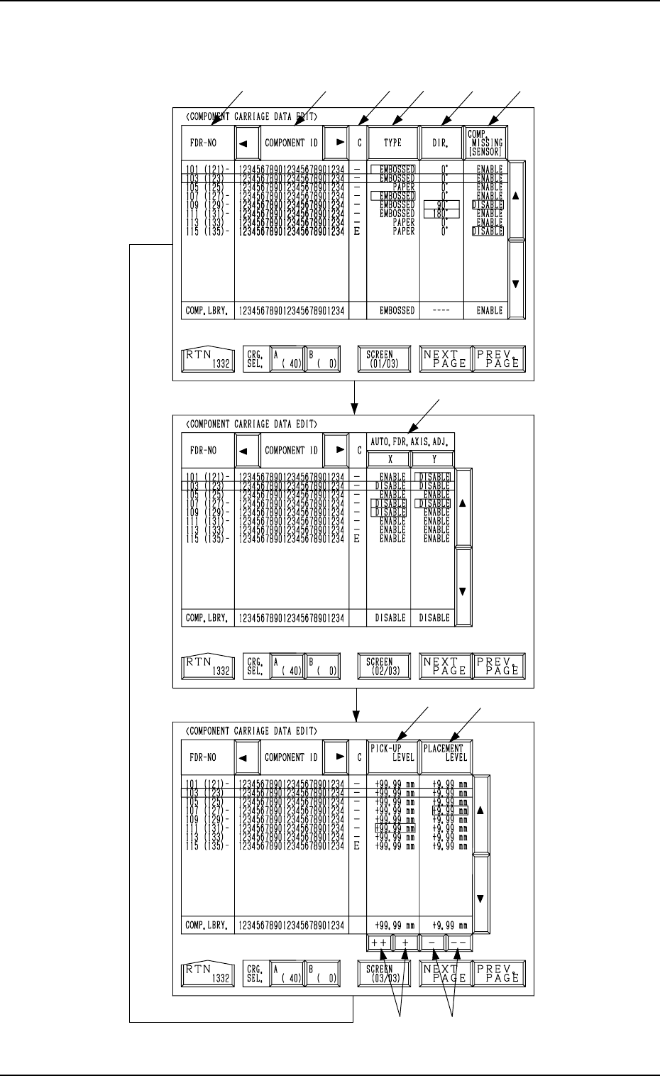
[SCREEN (XX/XX)] key
Fig. 3.20-2
Fig. 3.20-3
9910-001 3-37 Tg0246-PM-OP
Every time the [SCREEN (XX/XX)] key is pressed, another display appears
on the screen.