1OM-1064-002.pdf - 第113页
2. Hierarchical Structure of Operation Displays Fig. 2.8 Fig. 2.9 Fig. 2.10 Fig. 2.12 Fig. 2.1 1 2. Hierarchical Structure of Operation Displays 2.1 MAIN MENU Display (1) Press the [POWER ON] button on the operation pane…
1. Notes
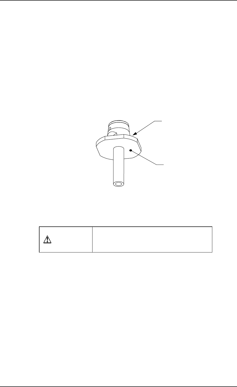
1.7 Vacuum Nozzles
Do not apply oil, etc., to the diffusion plate.
• Note that sebum nor oil, etc., should not adhere to Plane A (Fig. 2.7) of the
diffusion plate.
If sebum or oil adheres to Plane A, the recognized image will look uneven,
causing a component recognition error.
Avoid nicking the diffusion plate.
• Do not hold the diffusion plate while cleaning the vacuum nozzle. Wipe off
dirt and dust with a rag or blow them off with an air gun.
Note that a component recognition error might occur when the diffusion
plate is nicked.
Don’t put a magnet near the vacuum nozzle.
CAUTION
When handling the removed vacuum nozzle,
be careful not to magnetized, trouble will oc-
cur during pick-up and placement procedure.
Diffusion Plate
A
0004-002 2-14 Tg0246-PM-OP
Fig. 2.7
2. Hierarchical Structure of Operation Displays
Fig. 2.8
Fig. 2.9
Fig. 2.10
Fig. 2.12
Fig. 2.11
2. Hierarchical Structure of Operation Displays
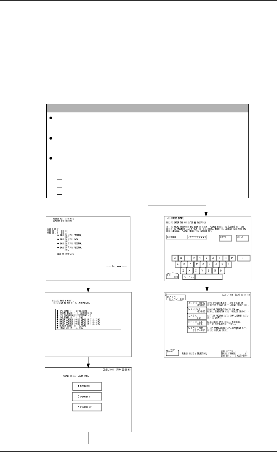
2.1 MAIN MENU Display
(1) Press the [POWER ON] button on the operation panel.
(2) Select “Log In” type at the log-in selection display. (Hierarchical Sequence:
“INITIALIZATION” Display (Figs. 2.8 and 2.9) → Log-In Selection Dis-
play (Fig. 2.10))
(3) Enter the password at the “PASSWORD ENTRY” display (Fig. 2.11)
and press the [ENTER] key.
(4) The “MAIN MENU” display (Fig. 2.12) appears on the screen.
Reference
When no password is set, the “MAIN MENU” display appears on the
screen without going through the “PASSWORD ENTRY” display.
Refer to “3. Management of Password of Secton 4 in Volume 4” for the
password setting.
A mark (a color code) appears at the upper left corner of all displays,
clarifying the selected “Log In” type.
S (Red) : For Supervisor
1 (Yellow) : For Operator #1
2 (Light Green) : For Operator #2
9910-001 2-15 Tg0246-PM-OP
2. Hierarchical Structure of Operation Displays
9910-001 2-16 Tg0246-PM-OP
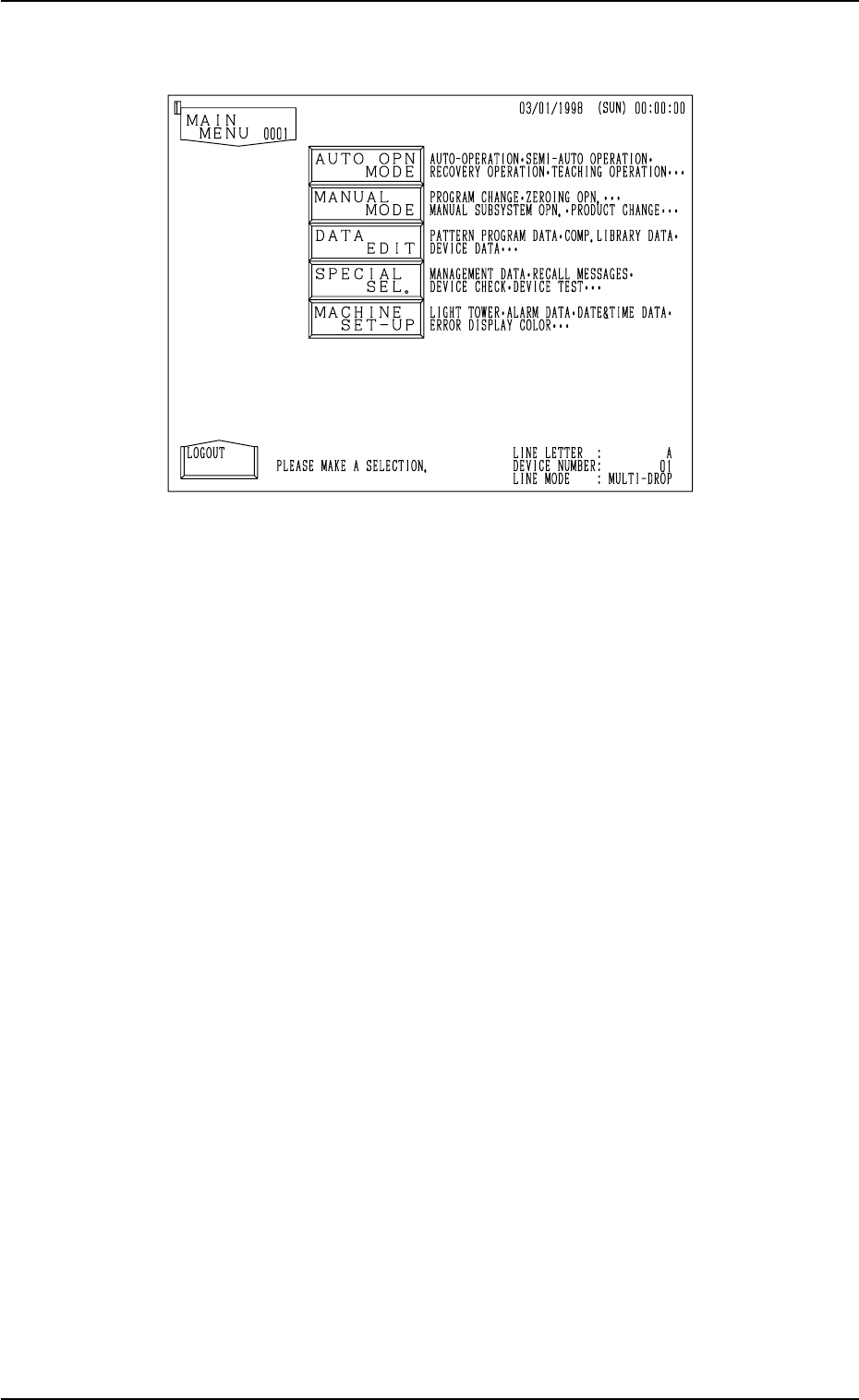
The “MAIN MENU” display can be assumed as the trunk of a tree and looks
as shown in Fig. 2.13.
Fig. 2.13
This display is provided with five keys, enabling the operator to select each
display according to your desired operation or purpose.
[AUTO OPN MODE] Key
This option is mainly used for automatic operation and consists of labels
(designation of automatic operation, automatic operation step, etc.) related
to automatic operations based upon the pattern program data.
[MANUAL MODE] Key
This option is mainly used for set-up operations and consists of the labels
such as program change, zeroing operation, manual selection, etc.
[DATA EDIT] Key
This option consists of labels for data editing (pattern program data, compo-
nent library data, device data, offset data, etc.).
[SPECIAL SEL.] Key
This option consists of labels (management data, recall messages, device
check (input check), teaching operation, etc.) related to machine mainte-
nance and inspections.
[MACHINE SET-UP] Key
This option consists of labels related to machine set-up operations which
enable the operator to set a password, the tower lights, buzzer, calendar,
error indicating colors, monitor, etc.