1OM-1064-002.pdf - 第69页
(3) The deviation of the positioned P .C.B. is detected by the P .E.C. recogni- tion function and the machine performs component pick-up and place- ment operation according to the programmed data (pattern program). The m…
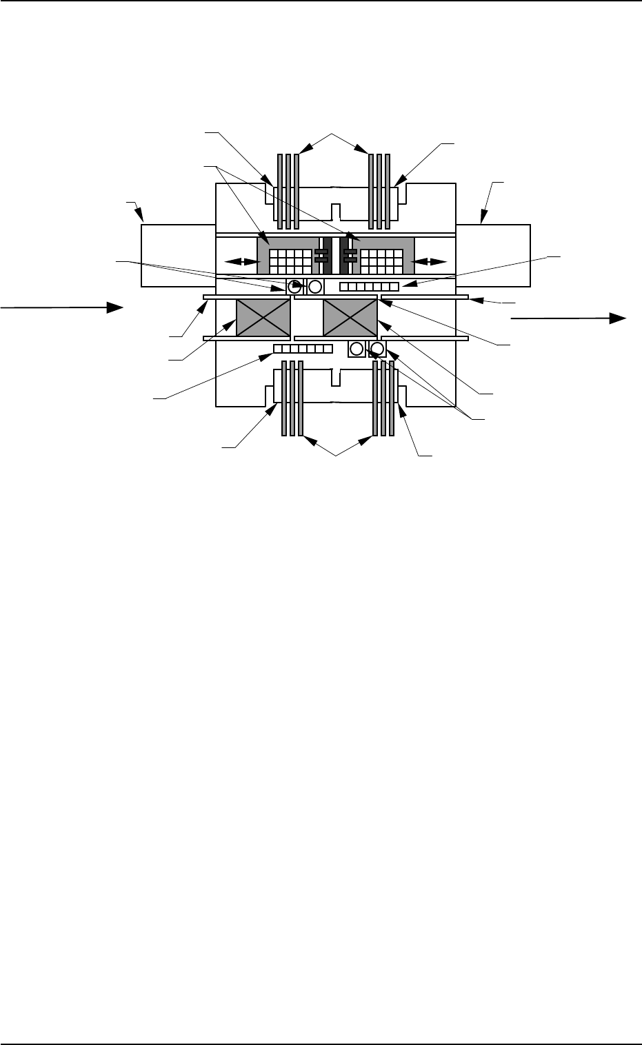
Fig. 1.14 P.C.B. Flow (From Left to Right)
6. Outline of System Operation
0004-002 1-38 Tg0246-PM-OP
6. Outline of System Operation
6.1 Perspective
(1) The P.C.B. sent to L conveyer is transferred from the input machine to the
standby position in Fig. 1.14.
(2) The P.C.B. at the standby position is transferred to the P.C.B. positioning
section and positioned there after the component-placed P.C.B. at the P.C.B.
positioning section is sent to the R conveyor.
Multi-Layer Tray Feeder L
(Option)
Multi-Layer Tray Feeder R
(Option)
Feeder Base #1
Feeder Base #2
Tape Feeder (Vibratory Stick Feeder)
Feeder Base #4
Feeder Base #3
Ta
p
e Feeder
Nozzle Stocker
Component Recognition Camera
Nozzle Stocker
Component
Recognition Camera
Tray Palette
R Conveyor
P.C.B. Positioning Section
L Conveyor
Standby Position
P Conveyor
(P.C.B. Positioning
Section)
(Front Side of Machine)
P.C.B. Flow Direction
(Input Machine)
(Output Machine)

(3) The deviation of the positioned P.C.B. is detected by the P.E.C. recogni-
tion function and the machine performs component pick-up and place-
ment operation according to the programmed data (pattern program).
The machine performs component pick-up and placement operations in
the following order.
Case: Setting of Recognition before Component Pick-Up
(3.1) P.E.C. Recognition (Placement Position)
(3.2) Nozzle Change
(3.3) Component Picks from Feeder
(3.4) Component Recognition
When the result is “OK”, the system proceeds to (3.5).
When the result is “NG (No Good)”, the component is dis-
charged.
(3.5) Component Placement
The cycle of (3.2) through (3.5) is repeated alternately on both
A and B beams.
Case: Setting of Recognition after Component Pick-Up
(3.1) Nozzle Change
(3.2) Component Pick from Feeder
(3.3) Component Recognition
When the result is “OK”, the system proceeds to (3.4).
When the result is “NG (No Good)”, the component is dis-
charged.
(3.4) P.C.B. Recognition (Placement Position)
(3.5) Component Placement
The cycle of (3.2) through (3.4) is repeated alternately on both
A and B beams.
(4) The component-placed P.C.B. sent to the R conveyor is transferred to the
output machine by the R conveyor.
6. Outline of System Operation
0004-002 1-39 Tg0246-PM-OP
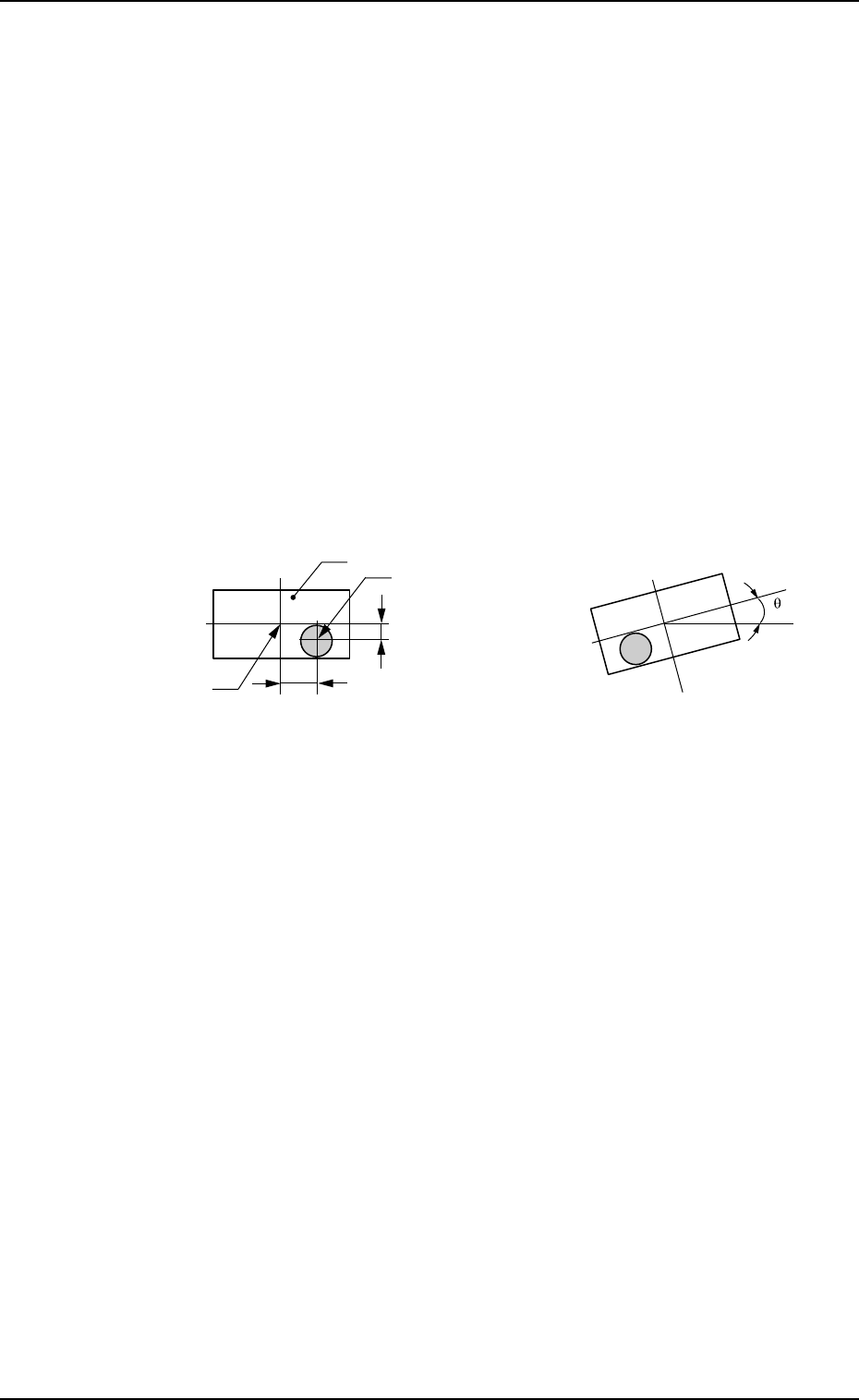
Component
Vacuum Nozzle
Center of Component
X
Y
6. Outline of System Operation
9910-001 1-40 Tg0246-PM-OP
6.2 Component Recognition
6.2.1 Scope
The machine is provided with three component recognition systems - “Back
Lighting Recognition System”, “Front Lighting Recognition System”, and
“Front Lighting (BGA) Recognition System”. The lighting method specified
in the component library is automatically selected.
The component recognition function is used to recognize the following three
items.
• Component Detection
All components can be detected.
• Component Inspection
Each inspection is made according to the component library.
• Measurement of Positional Deviation (X, Y) and Angular Deviation (θ)
between Centers of Recognition Camera and Component
Fig. 1.15 State of Component Picked Up by Vacuum Nozzle
Flow of Component Recognition
The component recognition is made using the component recognition camera.
↓
Angle correction is made.
↓
A component is placed on the P.C.B.
Fig. 1.15-1 Positional Deviation X, Y Fig. 1.15-2 Angular Deviation
θθ
θθ
θ
(deviation in correct direction)