1OM-1064-002.pdf - 第211页
7. T ray Pick-Up Matrix (Option) 7. T ray Pick-Up Matrix (Option) When the [TRA Y PICK-UP MA TRIX] key is pressed at the “AUTO OPN SUB-MENU” display , the following display appears on the screen. (Hierar- chical Sequence…
6. RECOVERY OPN. TEACHING OPN. Display
9910-001 3-41 Tg0246-PM-OP
6.4 FEEDER (B) OFFSET Display
When the [FEEDER (B) OFFSET] key is pressed at the “RECOVERY OPN.
TEACHING OPN.” display, the following display appears on the screen.
Note: The -marked item is optional.
Fig. 3.22
The feeder (B) offset data is used to correct the positional deviation in compo-
nent pick-up positions caused due to the variation in feeders.
Refer to “5.2.5 FEEDER (B) OFFSET Display of Section 2” for details.
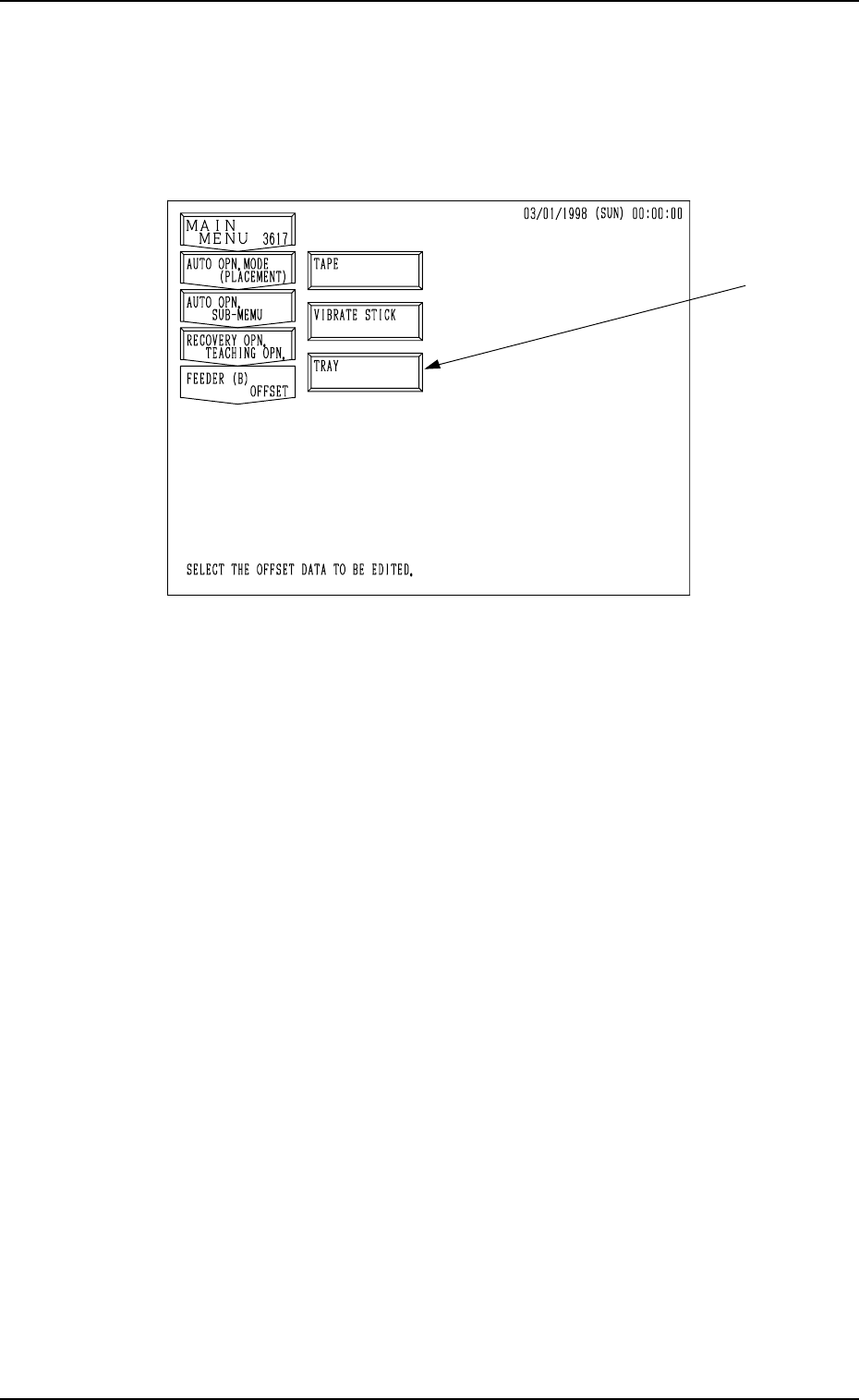
7. Tray Pick-Up Matrix (Option)
7. Tray Pick-Up Matrix (Option)
When the [TRAY PICK-UP MATRIX] key is pressed at the “AUTO OPN
SUB-MENU” display, the following display appears on the screen. (Hierar-
chical Sequence: “AUTO OPN MODE (PLACEMENT)” Display →
“AUTO
OPN SUB-MENU” Display)
*1
*2
*4
0103-003 3-42 Tg0246-PM-OP
Fig. 3.23
Press the [TRAY L] or the [TRAY R] key to select the multi-tray feeder L or R.
When the [TRAY L] or the [TRAY R] key is pressed, the following display or
the similar one appears on the screen.
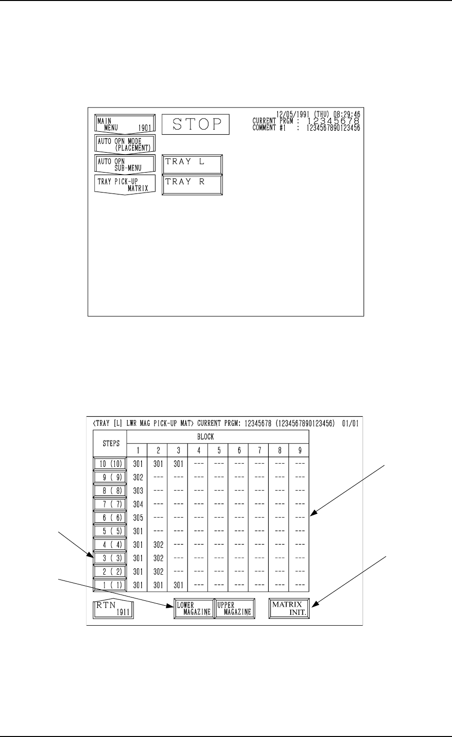
(In this example, the “TRAY [L] LWR MAG PICK-UP MAT” display is shown.
The display for “Tray R” looks like this.)
Fig. 3.24
*1
[STEPS] Keys
When one of the [STEPS] keys is pressed, the step of the upper or the
lower magazine corresponding to the key is selected.
The numbers represent the step Nos. (including the step offset).
The numbers in ( ) represent the actual step Nos.
*3
7. Tray Pick-Up Matrix (Option)
0103-003 3-43 Tg0246-PM-OP
*2 [LOWER MAGAZINE] and [UPPER MAGAZINE] Keys
Use one of these keys to select the steps of the upper or the lower magazine.
The selected key turns blue.
*3 [MATRIX INIT.]
Use this key to open the display (Fig. 3.28) where the tray pick-up matrix
data is initialized.
It is indicated, and will function, only when all initialization is available.
*4 BLOCK
Shown under the label “BLOCK” are the block feeder Nos. (FDR. NO.)
which are set for each individual steps.
Background Color of Block Feeder Nos. (FDR. NO.)
Table 3.2
Red This indicates that the block is short of components.
Green
This indicates that the block is used in the current pattern
program.
Black
This indicates that the block is not used in the current
pattern program.
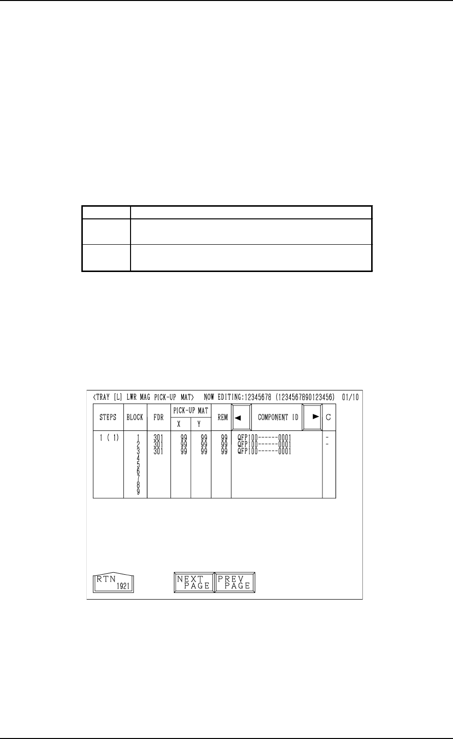
When the key indicated by *1 is pressed, the “TRAY [L] LWR MAG PICK-
UP MAT” display (the display for matrix indication/change) appears on the
screen.
• Case: The machine is in the “RUN” mode (including the “WAIT” mode).
Shown are the matrix positions of the tray components to be picked up
subsequently. (Fig. 3.25)
The matrix cannot be changed while the machine is running.
Fig. 3.25