1OM-1064-002.pdf - 第227页
Second Page First Page Fig. 4.6-1 Fig. 4.6-2 Third Page Fig. 4.6-3 5. Zeroing Operation When the [ZEROING OPERA TION] key is pressed at the “MANUAL MODE” display , the following display appears on the screen. When …
4.3 Overall Automatic Set-Up Function Interlinked
with Program Change
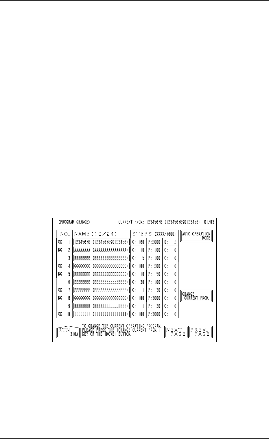
When the [MOVE] button is pressed at the “PROGRAM CHANGE” display
(Fig. 4.5), the devices for which “ON” is set in the “MODE” text boxes at the
“SET-UP DATA” display are all set up automatically right after the program
change is made. (Hierarchical Sequence: “DATA EDIT” Display → “PAT-
TERN PROGRAM” Display → “SET-UP DATA” Display)
The “PROGRAM CHANGE” display can be opened in the following
hierarchical sequences.
• “AUTO OPN MODE (PLACEMENT)” Display → “AUTO OPN. SUB-
MENU” Display →
• “MANUAL MODE” Display →
• “DATA EDIT” Display → “PATTERN PROGRAM” Display →
Note: When the [OPERATION/SET UP] switch is set to the “SET UP” side,
the set-up operation cannot be started.
Close the maintenance cover, the supply cover, and the safety bars and
set the [OPERATION/SET UP] switch to the “OPERATION” side for
safety purposes. Then, perform the program change operation.
Refer to “3. Program Change of Section 4” for details.
4. Product Change
Fig. 4.5
0004-002 4-10 Tg0246-PM-OP
Second Page
First Page
Fig. 4.6-1
Fig. 4.6-2
Third Page
Fig. 4.6-3
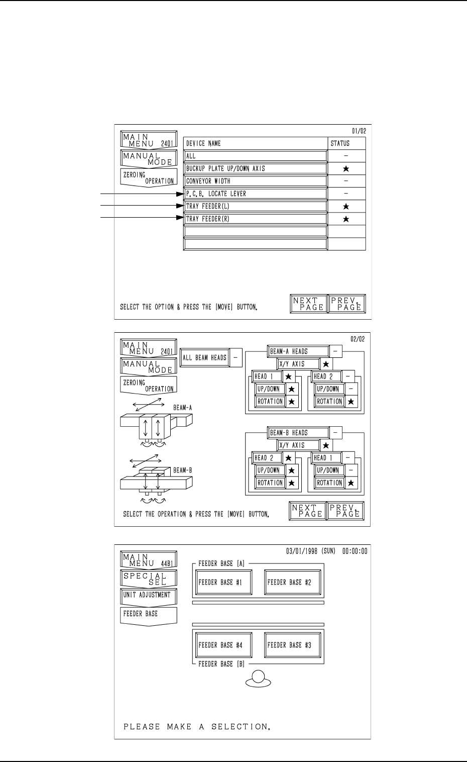
5. Zeroing Operation
When the [ZEROING OPERATION] key is pressed at the “MANUAL MODE”
display, the following display appears on the screen.
When the [NEXT PAGE] key is pressed, the next page opens. Pressing the
[PREV. PAGE] key opens the previous page.
Note: The -marked items are optional.
5. Zeroing Operation
9910-001 4-11 Tg0246-PM-OP

5. Zeroing Operation
Operation Procedure
(1) Select the device to be zeroed and press the [MOVE] button. The se-
lected device is zeroed.
(While the device is moving, the LED of the [MOVE] button illuminates.)
Ref.: Before the conveyor width set-up operation is initiated, each con-
veyor is automatically activated to check that no P.C.B. is located
at any irregular position.
(2) When the zeroing operation is completed, “” appears in the “STATUS”
text box.
(While the current position is being managed or indefinite, “-” appears in
the text box.)
Note: When a head is bypassed on each axis “Beam A” or “Beam B” or
the mechanical stopper of a beam is activated, nothing appears in
the text box, indicating that no axis can be selected.
• To zero all devices, select the [ALL] key and press the [MOVE] but-
ton.
All devices possible to be returned to their origins are zeroed.
Ref.: Pressing the [ZERO] button on the operation panel also zeroes all
devices.
Notes: (a) When the [OPERATION/SET UP] switch is set to the “SET
UP” side, the zeroing operation cannot be performed.
(b) The [CONVEYOR WIDTH] (conveyor width variable axis)
cannot be zeroed through the zeroing operation.
9910-001 4-12 Tg0246-PM-OP