1OM-1064-002.pdf - 第226页
4. 3 Overall Automatic Set-Up Function Interlinked with Program Change When the [MOVE] button is pressed at the “PROGRAM CHANGE” display (Fig. 4.5), the devices for which “ON” is set in the “MODE” text boxes at the “SET-…

Operation Procedure
(1) Select the [DESIGNATED WIDTH] key and press the [MOVE] button.
Activate the conveyor automatically to check that no P.C.B. is located at
any irregular position and then set up the conveyor width to “DESIG-
NATED WIDTH + CLEARANCE”.
Ref.: When the [DESIGNATED WIDTH] key is selected and a parameter
is entered, using the ten-key pad, the designated width data can be
changed.
• When “P.C.B. Width + Clearance” must be adjusted as a result after P.C.B.
transfer action is checked, select the [ (NARROW)] or the [ (WIDE)]
key and press the [MANUAL ALIGNMENT [MOVE]] key. Then, press the
[MOVE] button.
While the [MOVE] button is being pressed, the conveyor will inch to be
wider or narrower.
• To update the clearance data after the adjustment, press the [CLEARANCE
RESET] key.
The clearance data is changed to “Current Width - P.C.B. Size Y”.
Note: When the parameter exceeds ±5.0 mm, this operation cannot be per-
formed.
Ref.: The clearance data can be changed by selecting the [CONVEYOR
WIDTH CLEARANCE] key and entering a parameter with the ten-
key pad.
4. Product Change
0004-002 4-9 Tg0246-PM-OP
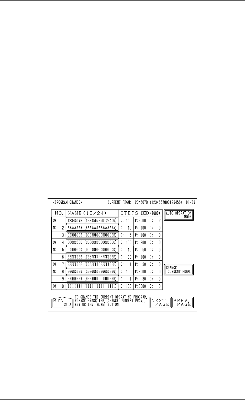
4.3 Overall Automatic Set-Up Function Interlinked
with Program Change
When the [MOVE] button is pressed at the “PROGRAM CHANGE” display
(Fig. 4.5), the devices for which “ON” is set in the “MODE” text boxes at the
“SET-UP DATA” display are all set up automatically right after the program
change is made. (Hierarchical Sequence: “DATA EDIT” Display → “PAT-
TERN PROGRAM” Display → “SET-UP DATA” Display)
The “PROGRAM CHANGE” display can be opened in the following
hierarchical sequences.
• “AUTO OPN MODE (PLACEMENT)” Display → “AUTO OPN. SUB-
MENU” Display →
• “MANUAL MODE” Display →
• “DATA EDIT” Display → “PATTERN PROGRAM” Display →
Note: When the [OPERATION/SET UP] switch is set to the “SET UP” side,
the set-up operation cannot be started.
Close the maintenance cover, the supply cover, and the safety bars and
set the [OPERATION/SET UP] switch to the “OPERATION” side for
safety purposes. Then, perform the program change operation.
Refer to “3. Program Change of Section 4” for details.
4. Product Change
Fig. 4.5
0004-002 4-10 Tg0246-PM-OP
Second Page
First Page
Fig. 4.6-1
Fig. 4.6-2
Third Page
Fig. 4.6-3
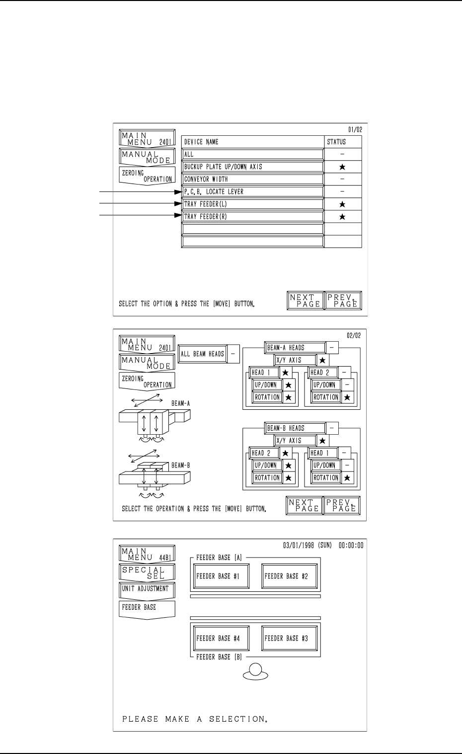
5. Zeroing Operation
When the [ZEROING OPERATION] key is pressed at the “MANUAL MODE”
display, the following display appears on the screen.
When the [NEXT PAGE] key is pressed, the next page opens. Pressing the
[PREV. PAGE] key opens the previous page.
Note: The -marked items are optional.
5. Zeroing Operation
9910-001 4-11 Tg0246-PM-OP