1OM-1064-002.pdf - 第104页
1. Notes 1.3 T ouch Screen • Since the touch screen uses the molecules in liquid crystals, do not apply strong pressure to the touch screen. T ry not to touch the screen except for input operations. The touch screen reac…
1. Notes
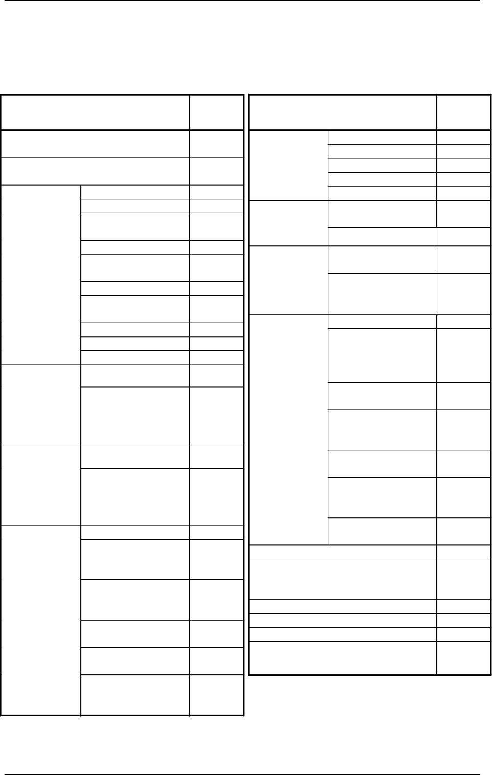
Operation Items
Operation
Possible/
Impossible
X Axis
×
Y Axis
×
Up/Down Shaft
×
Head Rotational Shaft
×
Manual Axis
Operation
Backup Up/Down Shaft
{
Movement to Target
Position
{
Set-Up
(Conveyor
Width)
Manual Axis Operation
{
Air Supply
(Beams A and B)
{
Manual
Subsystem
Operation
Pick-Up/Blowing
(LA1 and LA2 Axis,
LB1 and LB2 Axis)
{
P.C.B. Transfer
{
Backup Base
Movement
(Positioning, Standby,
and Origin Positions)
{
P.C.B. Locating Side
Clamp
{
L/P/R Conveyors
(Normal/Reverse
Rotation)
{
P/R Conveyor P.C.B.
Stopper
{
EL/ER Conveyors
(Normal/Reverse
Rotation)
{
Manual
Transfer
Operation
EL/ER Conveyer
P.C.B. Stopper
{
Teaching
×
Recognition Test
(P.C.B. and Component Recognition
Functions)
×
Automatic Operation
×
System Clear
×
ET Communication (RS-232C)
×
Tray Feeder (“Feeder Change-Over
Preparation Complete” Operation)
{
Operation Items
Operation
Possible/
Impossible
Operation on Available Operation Panel
Side
{
Operation on Unavailable Operation Panel
Side
×
Zeroing Operation
×
Backup Up/Down Shaft
{
Conveyor Width
Variable Shaft
{
Tray L and R
{
All Beams and Beams
A and B
×
X/Y Shaft
×
Head (Up/Down and
Rotational Shafts)
×
Up/Down Shaft
×
Head Rotational Shaft
×
Zeroing
Feeder Base
{
Traverse Shaft
{
Tray Feeder
Manual
Subsystem
Operation
(Zeroing
Operation)
Elevator Shaft
{
Traverse Shaft
{
Tray Feeder
Manual
Subsystem
Operation
(Manual
Operation)
Elevator Shaft
{
Tape Feed
{
L/P/R Conveyors
(Normal/Reverse
Rotation)
{
EL/ER Conveyors
(Normal/Reverse
Rotation)
{
Servomotor Adjustment
(X, Y)
×
Servomotor Adjustment
(L)
×
Unit Adjustment
Servomotor Adjustment
(Backup Up/Down
Shaft)
{
Case: The [OPERATION/SET UP] switch is set to the “SET UP”
side.
{ : Operation Possible
× : Operation Impossible
9910-001 2-5 Tg0246-PM-OP
1. Notes
1.3 Touch Screen
• Since the touch screen uses the molecules in liquid crystals, do not apply
strong pressure to the touch screen.
Try not to touch the screen except for input operations.
The touch screen reacts to the force of 0.78N (80g) or less.
Do not press the screen with an excessive force.
CAUTION
The surface of the touch screen is fragile. Do
not rub the surface nor touch it with a pen, a
screwdriver, etc.
CAUTION
The machine is not a water-proof and encap-
sulated type.
Avoid dust, water droplet, oil droplet, metal
pieces.
Especially, when metal pieces or combustible
material are mixed into the machine, it may lead
to fire ignition.
• When power is supplied to the machine at low temperature, the brightness
of the back light deteriorates but resumes normal in a few minutes.
The deterioration is not abnormal.
When the back light is turned on or off repeatedly at low temperature, the
life will be shortened.
• Caution before Touch Screen Cleaning
CAUTION
Turn off the operation power before the touch
screen is cleaned.
Cleaning the screen while it is active may cause
adverse reaction of the screen, resulting in data
corruption.
When the surface of the touch screen is stained, wipe off dust and dirt with a
dry cloth.
Do not use alcohol, benzene, etc.
CAUTION
Do not use alcohol or benzene to clean the
touch screen.
Otherwise, the surface of the touch screen may
melt or get cloudy.
• To Correct the Drift of the Touch Screen Sensors
The touch screen sensors should be adjusted to compensate for the drift
between the reacting part of the touch screen sensors and the screen images.
Refer to “Section 5 Touch Screen in Volume 4” for the adjustment.
0004-002 2-6 Tg0246-PM-OP
1. Notes
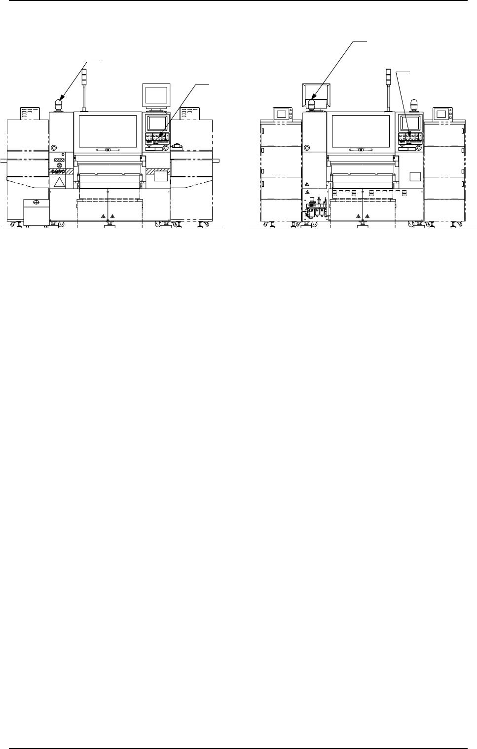
1.4 Component Shortage Indicator
Component Shortage
Indicator (A)
[READY]
Button
[READY] Button
Component Shortage Indicator (B)
(Front View) (Beam B Side) (Rear View) (Beam A Side)
1. Notes
0004-002 2-7 Tg0246-PM-OP
Fig. 2.1
This indicator shows that a feeder on the feeder base is short of components.
• Component Shortage Indicator ON
When component supply to the feeder is completed and the X/Y beam on
the related side is available in operation, the component shortage indicator
illuminates.
• Component Shortage Indicator OFF
When components are not picked up from the related side according to the
current pattern program, the component shortage indicator extinguishes.
• Component Shortage Indicator “Flickering” (The indicator flickers only when
components are picked up from the related side according to the current
pattern program.)
When the operation on the related side cannot be continued due to a compo-
nent shortage error during operation, the component shortage indicator flick-
ers, indicating that the feeder can be replaced or replenished with compo-
nents.
When the [READY] button is pressed after the feeder replacement or com-
ponent supply is completed, the component shortage indicator keeps on flick-
ering until the machine is set in the “READY” mode.
When the [READY] button is pressed and the electromagnetic locks of the
supply cover and the safety bar are released, the component shortage indica-
tor flickers, indicating that the feeder can be replaced or replenished with
components.
Note: When the [OPERATION/SET UP] switch is set to the “SET UP” side,
the operation on the available side is locked and the electromagnetic
locks of the supply cover and the safety bar are latched forcibly and
both the LED of the [READY] button and the component shortage
indicator flicker. (Only when components are picked up from the op-
posite side according to the current pattern program)