1OM-1064-002.pdf - 第23页
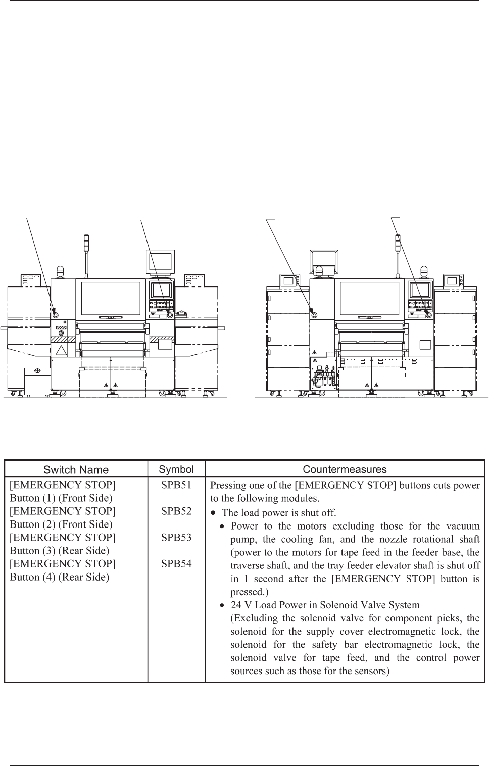
[EMERGENCY ST OP] Button (1) SPB51 [EMERGENCY STOP] Button (2) SPB52 [EMERGENCY ST OP] Button (4) SPB54 [EMERGENCY ST OP] Button (3) SPB53 3. Safety Switches 0304-002 21 Tg0246-PM-OP (Front View) (Side B) (Rear View) (Si…
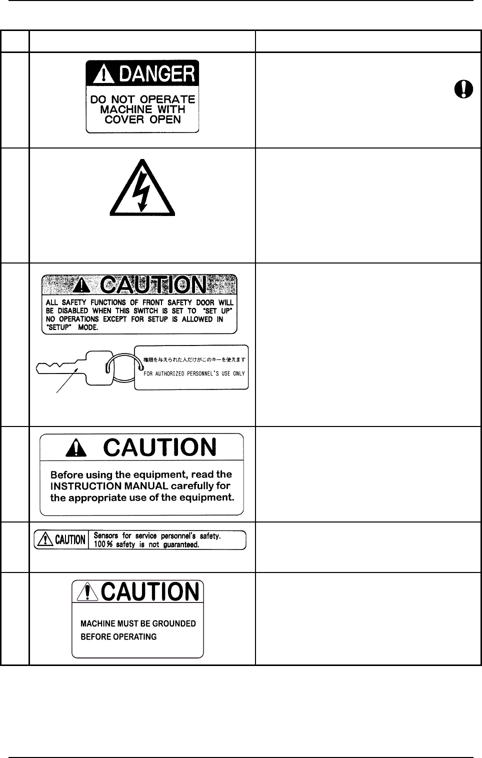
No. Warning Labels Description
*7 • Do not operate the machine with the cover
opened.
*8 • Do not touch any internal sections of the ma-
chine.
• Before maintenance, inspection, adjustment
work, etc., on internal sections, turn off the
power switch and the air source of the machine.
Only qualified personnel should operate the
machine, and following the specified instruc-
tions.
*9 • The interlock functions of the safety door will
be disabled when the [OPERATION/SET UP]
switch is set to “SET UP” side. Special caution
is required to avoid any danger.
• No operations except for setup is allowed in
“SET UP” mode.
• Do not keep the selection key inserted unless
necessary. The key shall be stored by the per-
son in charge.
*10 • Please read the instruction manual carefully
before operating the machine.
*11 • Sensors for service personnel’s safety.
(100% safety is not guaranteed.)
*12 • Be sure to connect a ground wire correctly to
avoid electric shock.
Key (for the [OPERATION/SET UP] Switch)
2.2 Warning Label Description
9910-001 20 Tg0246-PM-OP
[EMERGENCY STOP]
Button (1)
SPB51
[EMERGENCY STOP]
Button (2)
SPB52
[EMERGENCY STOP]
Button (4)
SPB54
[EMERGENCY STOP]
Button (3)
SPB53
3. Safety Switches
0304-002 21 Tg0246-PM-OP
(Front View) (Side B) (Rear View) (Side A)
3. Safety Switches
• When an error is detected in the machine, the safety features are de-
signed to stop the dangerous moving mechanisms of the machine.
Everything is processed on the machine side (hardware) without using any
software application on the computer side.
3.1 [EMERGENCY STOP] Buttons
Press one of the [EMERGENCY STOP] buttons to stop the machine immedi-
ately in an emergency. The power is turned off and the machine stops running
immediately.
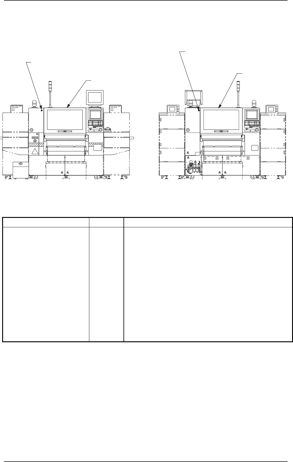
[Maintenance Cover B Detection] Switch
SQ084
Maintenance Cover
Maintenance
Cover
[Maintenance Cover A Detection] Switch
SQ083
0304-003 22 Tg0246-PM-OP
3.2 Maintenance Cover Check Switches
(Front View) (Side B) (Rear View) (Side A)
3.2 Maintenance Cover Check Switches
When the mainte nance cover detected open, the load power is shut off.
Switch Name
Symbol Countermeasures
Maintenance Cover A
Detection (Rear View)
Maintenance Cover B
Detection (Front View)
SQ083
SQ084
Opening either of the maintenance covers cuts power to the
following modules.
•
The load power is shut off.
•
Power to the motors excluding those for the vacuum
pump, the cooling fan, and the nozzle rotational shaft
(power to the motors for tape feed in the feeder base, the
traverse shaft, and the tray feeder elevator shaft is shut
off in 1 second after the safety door is opened.)
•
24 V Load Power in Solenoid Valve System
(Excluding the solenoid valve for component picks, the
solenoid for the supply cover electromagnetic lock, the
solenoid for the safety bar electromagnetic lock, the
solenoid valve for tape feed, and the control power sources
such as those for the sensors)