1OM-1064-002.pdf - 第189页
5. Operation Mode D A B 5.1 AUT OMA TIC FEEDER AXIS ADJUSTMENT MODE Display • The difference between the nozzle and component center positions calcu- lated at component recognition is corrected using statistical processi…
5. Operation Mode
*1
*2
*3
*4
*5
*6
5. Operation Mode
• Basically parameters for operation mode are set in the current pattern pro-
gram data. When some of the parameters (feeder alternate cancel, etc.) must
be modified according to situational changes and the required menu key is
pressed at the “OPERATION MODE” display, the corresponding display
opens, enabling the alteration of parameters set in the data boxes labeled
such as “RECOVERY MODE” (reserved function), etc.
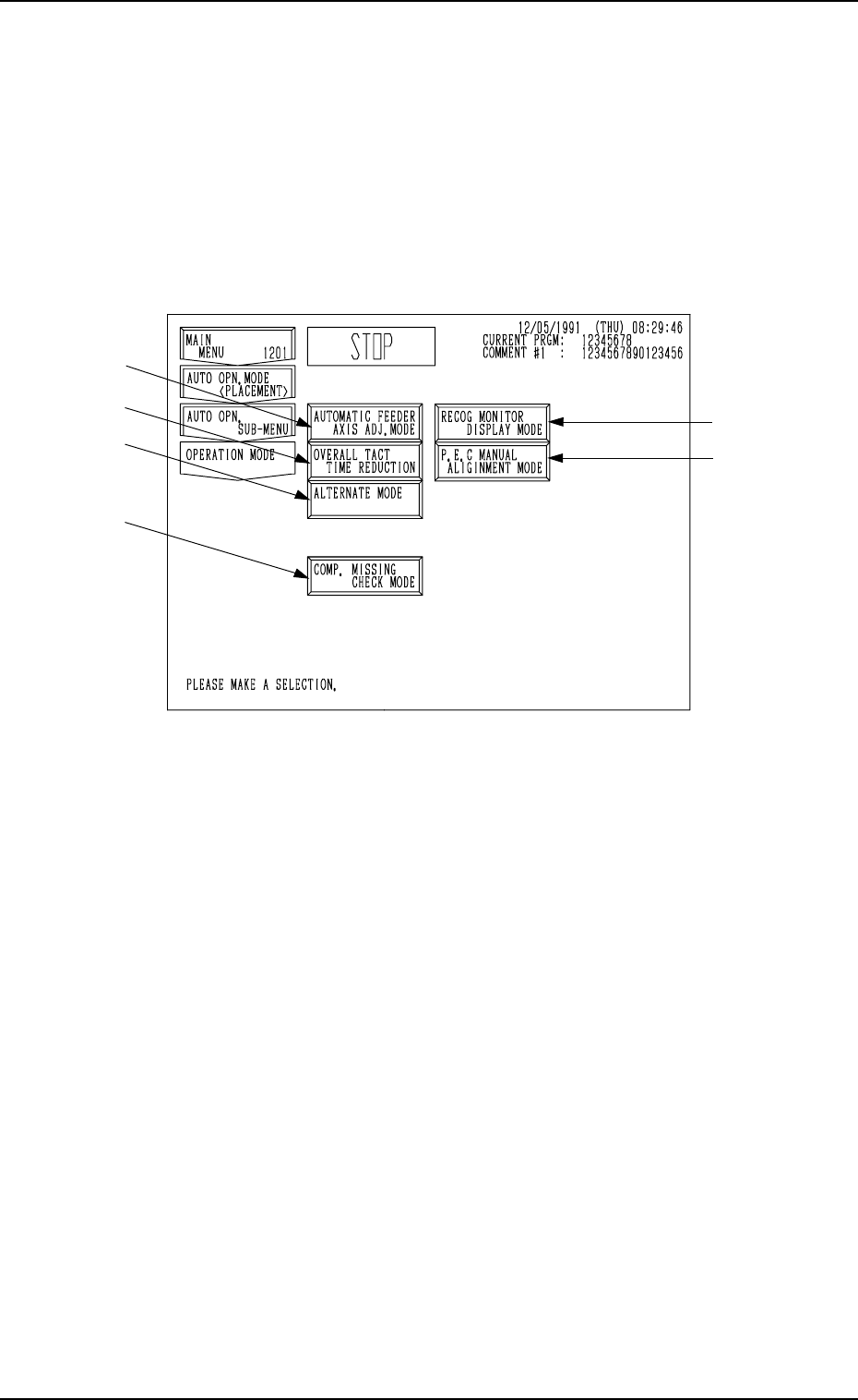
When the [OPERATION MODE] key is pressed at the “AUTO OPN. SUB-
MENU” display, the following display appears on the screen.
Fig. 3.6
*1 [AUTOMATIC FEEDER AXIS ADJ. MODE] Key
“ENABLE” or “DISABLE” can be set in the “AUTOMATIC FEEDER
AXIS SETTING (X) DIR.” and “AUTOMATIC FEEDER AXIS SETTING
(Y) DIR.” data boxes. The function to learn and follow up the feeder (B)
offset using statistical processing can be set to correct positional deviation
of component picks caused due to variations in feeders.
*2 [OVERALL TACT TIME REDUCTION] Key
This key enables the setting of upper limit of the overall tact time (covering
the operation speed of each device for coordination) specified in the com-
ponent library data.
*3 [RECOG MONITOR DISPLAY MODE] Key
When this key is pressed, the “RECOG MONITOR DISPLAY MODE”
display appears on the screen, enabling the selection of how to display the
results of recognition such as P.E.C. and component recognition functions.
*4 [P.E.C. MANUAL ALIGNMENT MODE] Key
When this key is pressed, the “P.E.C. MANUAL ALIGNMENT MODE”
display appears on the screen, enabling the designation of the manual align-
ment mode to cope with a P.E.C. recognition error.
*5 [ALTERNATE MODE] Key
When this key is pressed, the “ALTERNATE MODE” display appears on
the screen, enabling the operator to determine whether or not the alternate
feeder mode should be used.
*6 [COMP. MISSING CHECK MODE] Key
When this key is pressed, the “COMPONENT MISSING CHECK MODE”
display appears on the screen, enabling the operator to determine whether
or not the component missing check mode should be used.
9910-001 3-19 Tg0246-PM-OP
5. Operation Mode
D
A
B
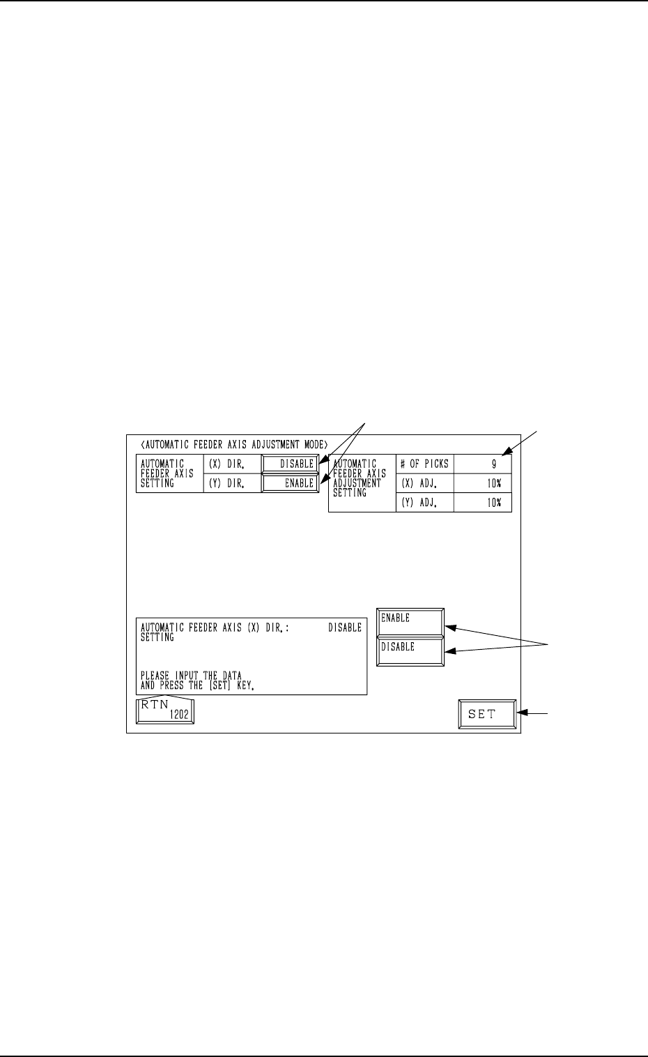
5.1 AUTOMATIC FEEDER AXIS ADJUSTMENT MODE
Display
• The difference between the nozzle and component center positions calcu-
lated at component recognition is corrected using statistical processing based
on the automatic feeder axis adjustment setting specified in the automatic
operation set-up data. This key enables the overall cancellation of the func-
tion to follow up and correct the feeder (B) offset data for all feeders.
• “ENABLE” or “DISABLE” can be set individually in the “AUTOMATIC
FEEDER AXIS SETTING (X) DIR.” and “AUTOMATIC FEEDER AXIS
SETTING (Y) DIR.” data boxes.
Note: Use the component library data to cancel the automatic feeder axis
adjustment function for the specific feeder.
When the [AUTOMATIC FEEDER AXIS ADJ. MODE] key is pressed at the
“OPERATION MODE” display, the following display appears on the screen.
Note: When the machine is set in the “RUN” or “WAIT” mode, the data save
operation (saving of changed setting) cannot be performed.
Fig. 3.7
Operation Procedure
(1) Select one of the data boxes A.
(2) Select either one of the option keys B and press the [SET] key C.
Note: The parameters set in the automatic operation set-up data appear
in the “AUTOMATIC FEEDER AXIS ADJUSTMENT SET-
TING” data boxes D.
C
0004-002 3-20 Tg0246-PM-OP
5. Operation Mode
B
C
A
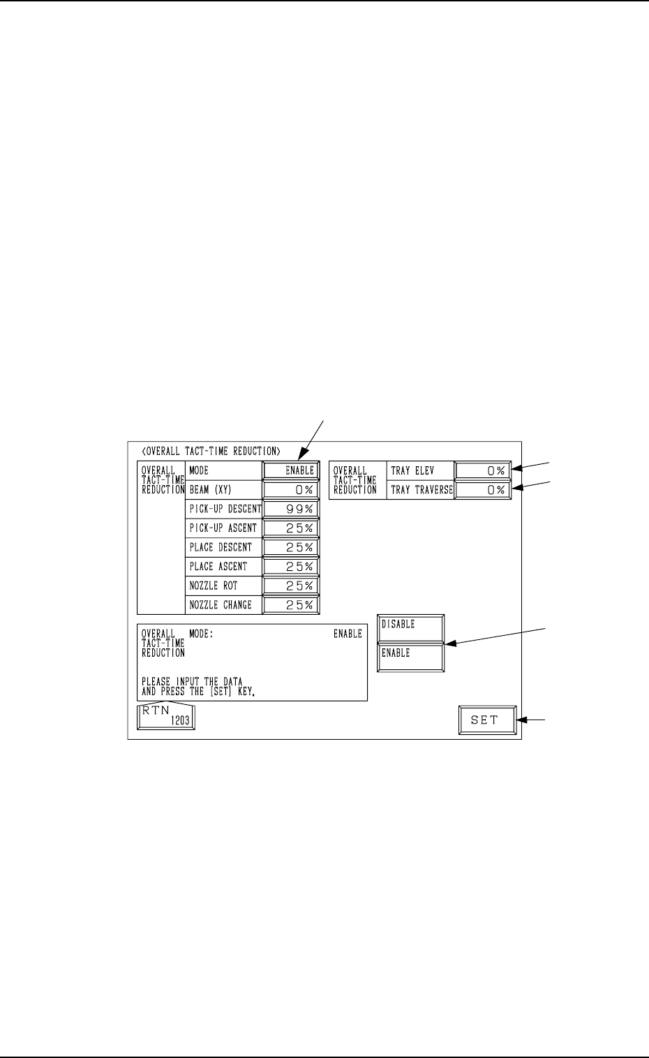
5.2 OVERALL TACT-TIME REDUCTION Display
• The upper limit of the tact time specified in the component library data can
be set in coordination with the working speed of each device (rate of speed
reduction based on the highest speed) specified in the component library
data.
• If a higher speed than that specified here is set in the component library
data, it is regulated to the specified upper limit for all components.
• If a lower speed than the upper limit is set in the component library data, it
becomes valid for such components.
• When there is still some room in the placement tact time according to the
line balance, the machine can be operated at a slow tact time with each
device movement slowed down.
When the [OVERALL TACT TIME REDUCTION] key is pressed at the “OP-
ERATION MODE” display, the following display appears on the screen.
Note: The -marked functions are optional.
Fig. 3.8
0004-002 3-21 Tg0246-PM-OP