1OM-1064-002.pdf - 第213页
7. T ray Pick-Up Matrix (Option) 0103-001 3-43-1 Tg0246-PM-OP Red This indi cates that t he block is short of com ponents. Green This indicates that the block i s used in the curren t pattern program . White This indicat…
7. Tray Pick-Up Matrix (Option)
0103-003 3-43 Tg0246-PM-OP
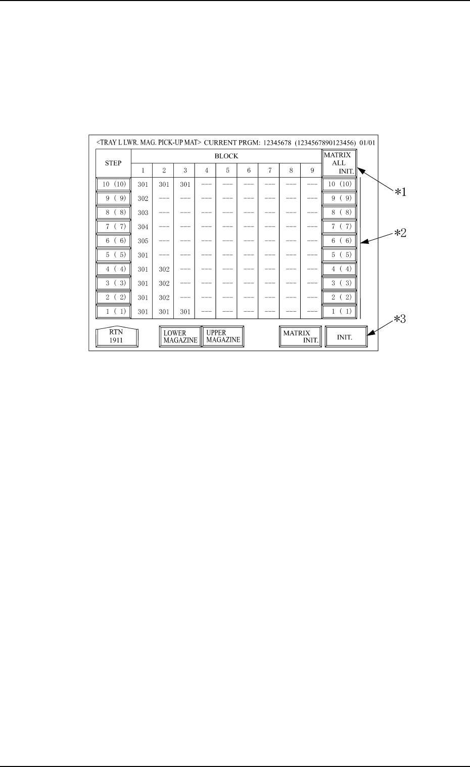
*2 [LOWER MAGAZINE] and [UPPER MAGAZINE] Keys
Use one of these keys to select the steps of the upper or the lower magazine.
The selected key turns blue.
*3 [MATRIX INIT.]
Use this key to open the display (Fig. 3.28) where the tray pick-up matrix
data is initialized.
It is indicated, and will function, only when all initialization is available.
*4 BLOCK
Shown under the label “BLOCK” are the block feeder Nos. (FDR. NO.)
which are set for each individual steps.
Background Color of Block Feeder Nos. (FDR. NO.)
Table 3.2
Red This indicates that the block is short of components.
Green
This indicates that the block is used in the current pattern
program.
Black
This indicates that the block is not used in the current
pattern program.
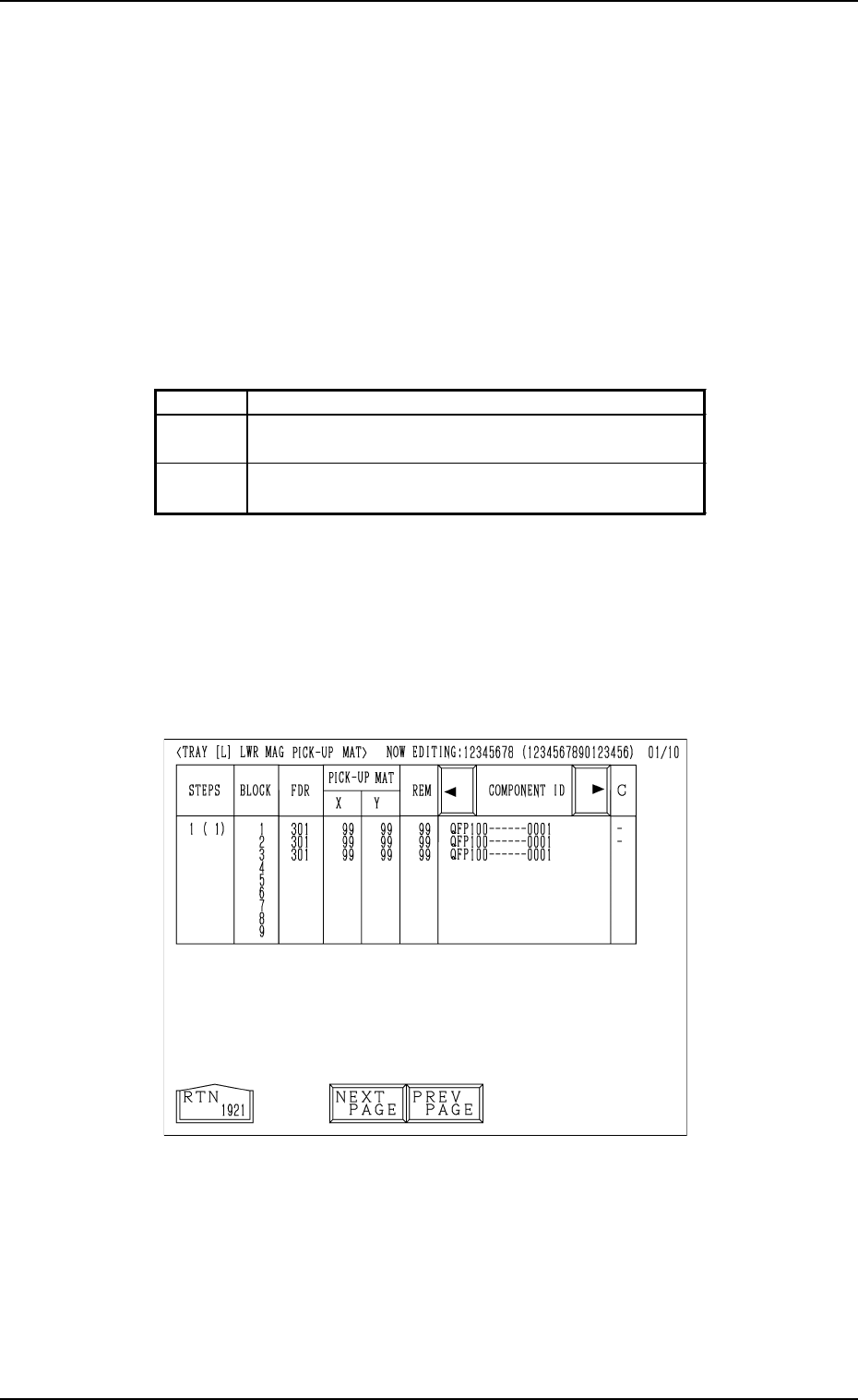
When the key indicated by *1 is pressed, the “TRAY [L] LWR MAG PICK-
UP MAT” display (the display for matrix indication/change) appears on the
screen.
• Case: The machine is in the “RUN” mode (including the “WAIT” mode).
Shown are the matrix positions of the tray components to be picked up
subsequently. (Fig. 3.25)
The matrix cannot be changed while the machine is running.
Fig. 3.25

7. Tray Pick-Up Matrix (Option)
0103-001 3-43-1 Tg0246-PM-OP
Red This indicates that the block is short of components.
Green
This indicates that the block is used in the current pattern
program.
White
This indicates that the block is not used in the current
pattern program.
Shown are the feeder Nos. (FDR. NO.), the pick-up matrix positions,
the remaining number of components, and the component IDs which
belong to each individual blocks.
Foreground Color of Feeder Nos. (FDR. NO.)
Table 3.3
7. Tray Pick-Up Matrix (Option)
0103-002 3-44 Tg0246-PM-OP
Tray Pick-Up Matrix Initialization
The tray pick-up matrix parameters are initialized all at once or for each
tray step.
When the [MATRIX INIT.] key is pressed at the display shown in Fig. 3.24,
the display shown in Fig. 3.28 appears.
Fig. 3.28
*1 [MATRIX ALL INIT.]
With this key, all the step selection switches for the magazine matrix
initialization, indicated on the display, are selected, or the selection is
cancelled.
* When all or some of the selection switches in the same step column for
the tray to be initialized are not selected, and the [MATRIX ALL
INIT.] switch is selected, then all selection switches for the magazine
matrix initialization in the same step column, are selected.
* When all the selection switches in the same step column for the tray
which is to be initialized are selected and the [MATRIX ALL INIT.]
switch is also selected, then the selection is can celled for all the above
selection switches.
Note: The selection of all switches at once for the magazine initializa-
tion or cancellation is available only for the magazines indicated
on thedisplay. The conditions for switches not indicated at the
display are not changed.
*2 Step No. Key (Selection Switch for the step to be initialized)
The step of the upper or lower magazine, to be initialized, is selected. The
figure shows step No., but it is shown at step offset.
Therefore, the actual step No. is shown in the brackets.