1OM-1064-002.pdf - 第230页
Second Page First Page Fig. 4.8-1 Fig. 4.8-2 7. Manual Axis Operation When the [MANUAL AXIS OPERA TION] key is pressed at the “MANUAL MODE” display , the following display appears on the screen. Every time the [NEXT P AG…
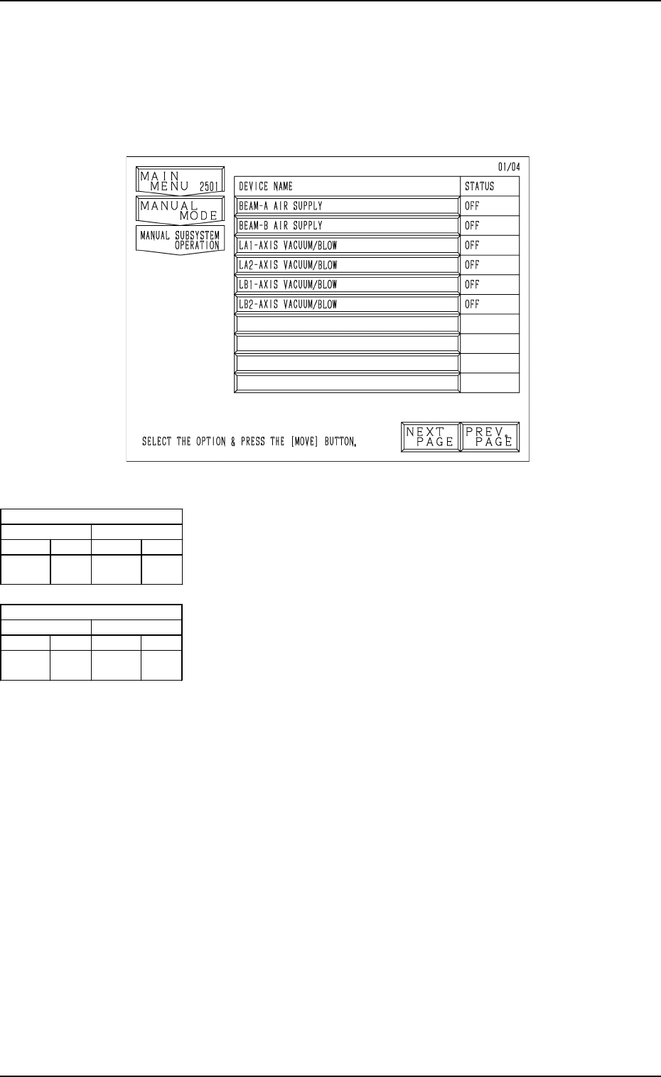
Fig. 4.7
[BEAM-A AIR SUPPLY] Key
When this key is selected and the [MOVE] button is pressed,
the source blow pressure open/close solenoid valves (C(A)-
YSV22) for LA1 and LA2 axis are turned ON or OFF.
[BEAM-B AIR SUPPLY] Key
When this key is selected and the [MOVE] button is pressed,
the source blow pressure open/close solenoid valves (C(B)-
YSV22) for LB1 and LB2 axis are turned ON or OFF.
[LA1-AXIS VACUUM/BLOW] Key
When this key is selected and the [MOVE] button is pressed,
the LA1-axis vacuum/blow solenoid valve (M(A1)-YSV21)
is turned ON or OFF.
[LA2-AXIS VACUUM/BLOW] Key
When this key is selected and the [MOVE] button is pressed,
the LA2-axis vacuum/blow solenoid valve (M(A2)-YSV21)
is turned ON or OFF.
[LB1-AXIS VACUUM/BLOW] Key
When this key is selected and the [MOVE] button is pressed,
the LB1-axis vacuum/blow solenoid valve (M(B1)-YSV21)
is turned ON or OFF.
[LB2-AXIS VACUUM/BLOW] Key
When this key is selected and the [MOVE] button is pressed,
the LB2-axis vacuum/blow solenoid valve (M(B2)-YSV21)
is turned ON or OFF.
Air Supply [OFF]
1 Axis 2 Axis
[OFF] [ON] [OFF] [ON]
No Pick-
Up/Blowing
Pick-
Up
No Pick-
Up/Blowing
Pick-
Up
Air Supply [ON]
1 Axis 2 Axis
[OFF] [ON] [OFF] [ON]
Blowing Pick-
Up
Blowing Pick-
Up
6. Manual Subsystem Operation
When the [MANUAL SUBSYSTEM OPERATION] key is pressed at the
“MANUAL MODE” display, the following display appears on the screen.
Each individual devices can be cycle-operated through manual operations at
this display.
6. Manual Subsystem Operation
9910-001 4-13 Tg0246-PM-OP
Second Page
First Page
Fig. 4.8-1
Fig. 4.8-2
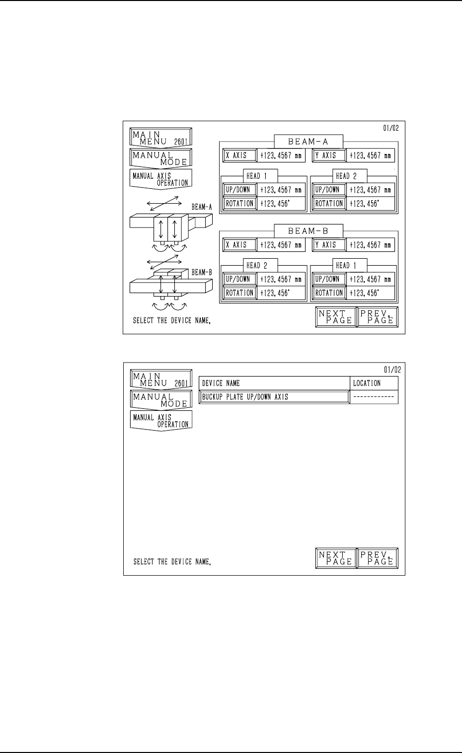
7. Manual Axis Operation
When the [MANUAL AXIS OPERATION] key is pressed at the “MANUAL
MODE” display, the following display appears on the screen.
Every time the [NEXT PAGE] or the [PREV. PAGE] key is pressed, another or
previous page appears on the screen.
• Select the device to be manually moved. The display for manual axis opera-
tion of the selected device appears on the screen.
Notes: (a) The [UP/DOWN] and [ROTATION] keys cannot be selected
when the head is bypassed (yellow).
Refer to “5. MANUAL BYPASS Display of Section 3 in Vol-
ume 4” for the detailed information on how to bypass a head
manually.
(b) The [X AXIS], [Y AXIS], [UP/DOWN], and [ROTATION] keys
cannot be selected when the X/Y beam is in the “ESCAPE”
mode (red).
7. Manual Axis Operation
9910-001 4-14 Tg0246-PM-OP
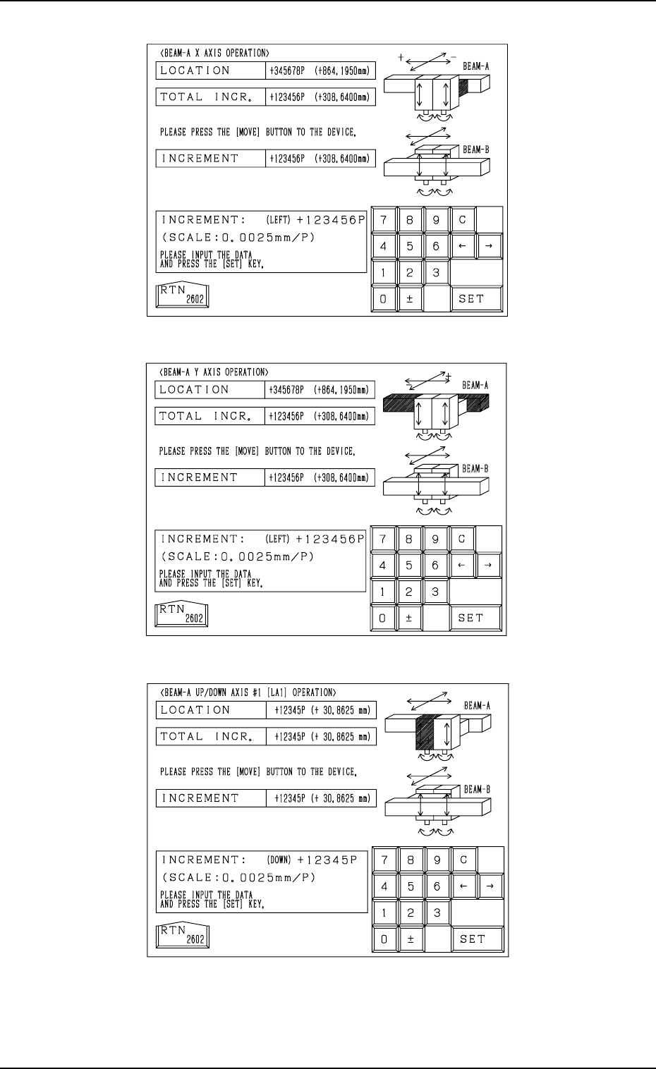
Fig. 4.9-1
Fig. 4.9-2
Fig. 4.9-3
7. Manual Axis Operation
9910-001 4-15 Tg0246-PM-OP
For X Axis on Beams A and B
For Y Axis on Beams A and B
For Up/Down Axis on Beams A and B