1OM-1064-002.pdf - 第159页
6. Starting, Emergency Stop, and T emporary Stop (Pause) Operations for Automatic Operation (“PLACE” Mode) • While the machine is exchanging data with an external device such as a programming device, the following messag…
6. Starting, Emergency Stop, and Temporary Stop (Pause) Operations for Automatic Operation (“PLACE” Mode)
6.6 Interruption of Automatic Operation
6.6.1 How to Interrupt the Automatic Operation
(1) Immediately after it is found that a wrong pattern program (due to wrong
selection of pattern program data or wrong program change operation) is
used as a current one after the machine starts automatic operation, press
the [PAUSE] button to stop the automatic operation temporarily.
(2) After the machine has stopped, press the [SYS CLR] button to interrupt
the operation in progress and reset the machine to the normal condition.
The automatic operation is interrupted.
6.6.2 Function of [SYS CLR] Button
The [SYS CLR] button has the following functions.
• When the [SYS CLR] button is pressed, the software is reset to the same
condition as that set at power-up (when power is supplied).
The hardware is not reset.
• When the [SYS CLR] button is pressed with the machine in the “PAUSE”
mode, the “PAUSE” mode is canceled and the machine is set to the “STOP”
mode.
Note: When the [SYS CLR] button is pressed, an error condition is released
simultaneously with cancellation of the “PAUSE” mode as described
above. To relieve an error condition, it is recommended that the [RE-
SET] button be pressed.
While data is being exchanged between the machine and the program-
ming device (option), the communication is not interrupted.
When the [OPERATION/SET UP] switch is set to the “SET UP” side,
the system clear operation cannot be performed.
CAUTION
When the [SYS CLR] button is pressed, the
recovery function (automatic repair of compo-
nent handling error) is also canceled.
When the [SYS CLR] button is pressed, only initialization of each P.C.B. is
performed.
Fig. 2.40
9910-001 2-60 Tg0246-PM-OP
6. Starting, Emergency Stop, and Temporary Stop (Pause) Operations for Automatic Operation (“PLACE” Mode)
• While the machine is exchanging data with an external device such as a
programming device, the following message is issued after No. 8 (sequence
# described in the above table).
Table 2.7
After the processing is over, the subsequent processing starts with No. 9.
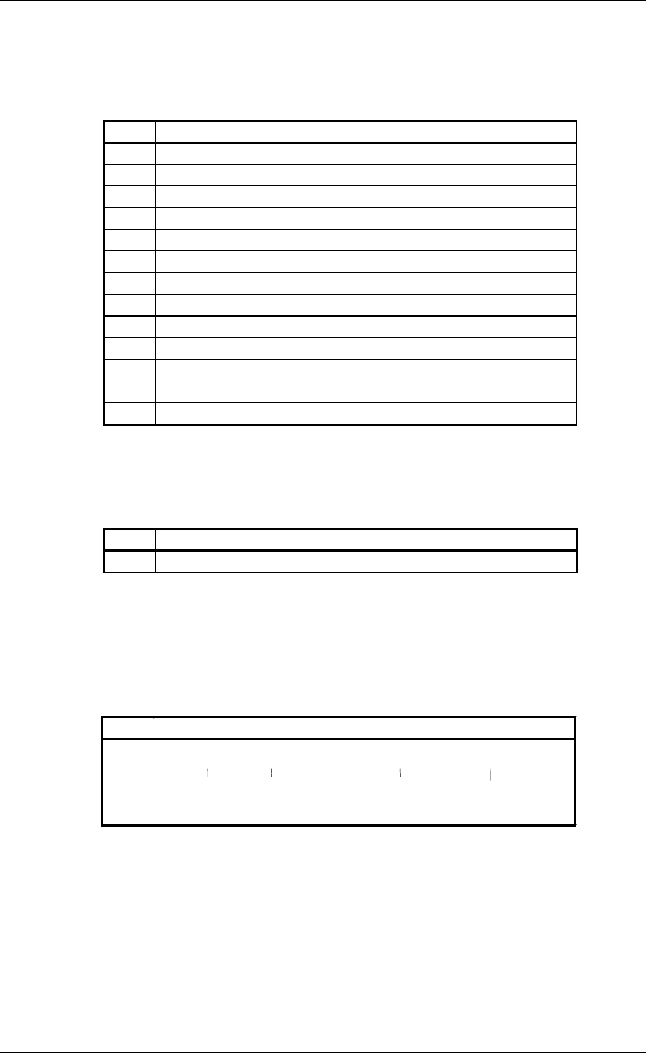
• When the recognition device has an abnormal element, the message and the
progress bar described in the table below appear while the sequence No. 12
is in progress and the recognition device is restarted.
Table 2.8
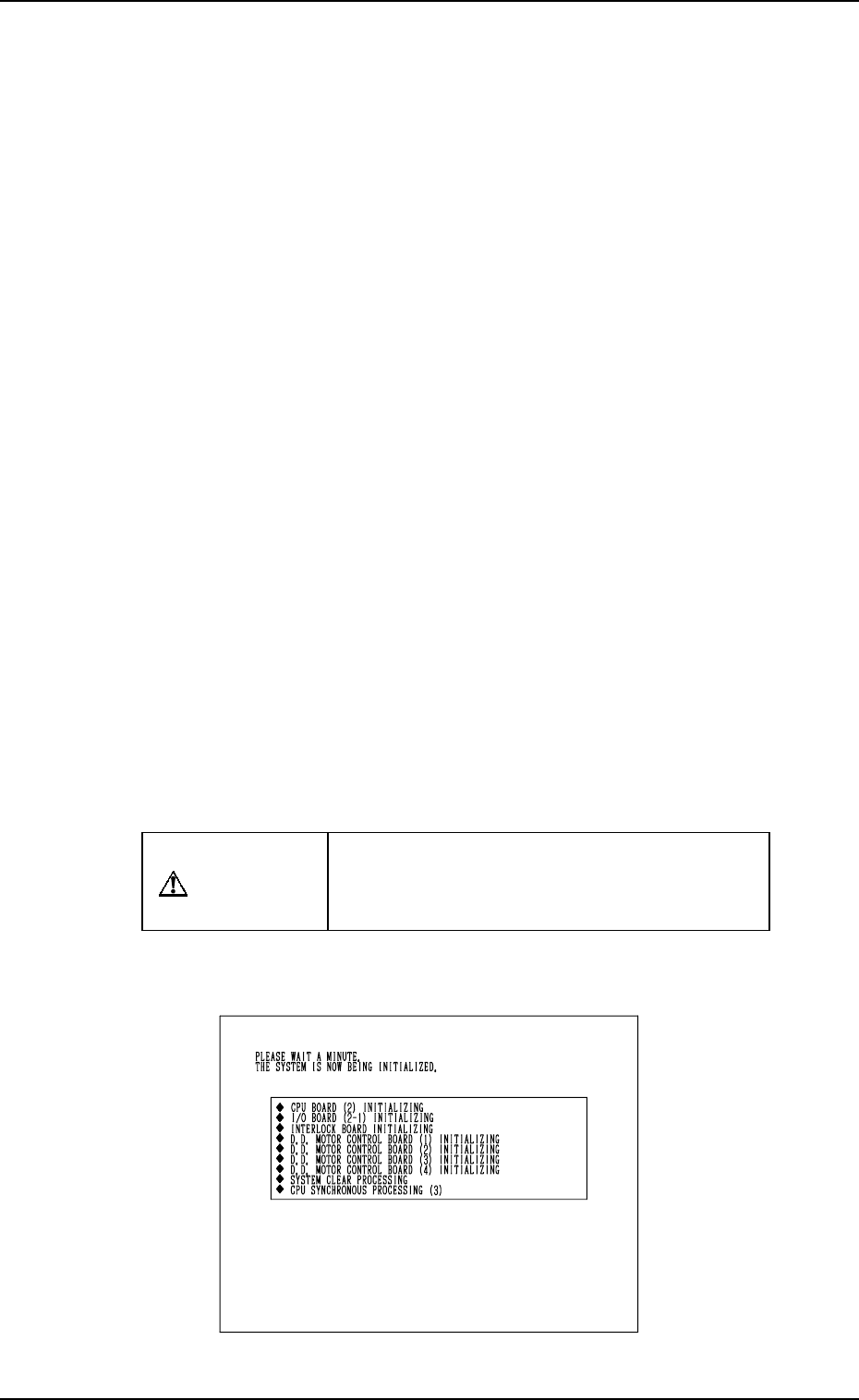
[Process Messages at System Clear]
The following messages are displayed (scrolled up) in the order described in
the table below.
Table 2.6
9910-001 2-61 Tg0246-PM-OP
No. Messa
g
e
8-1 WAITING FOR END OF COMM. WITH EXTERNAL DEVICE
No. Message
1 CPU P.C.B. (2) INITIALIZING
2 I/O BOARD (2-1) INITIALIZING
3 INTERLOCK BOARD INITIALIZING
4 D.D. MOTOR CONTROL BOARD (1) INITIALIZING
5 D.D. MOTOR CONTROL BOARD (2) INITIALIZING
6 D.D. MOTOR CONTROL BOARD (3) INITIALIZING
7 D.D. MOTOR CONTROL BOARD (4) INITIALIZING
8 SYSTEM CLEAR PROCESSING
9 CPU SYNCHRONOUS PROCESSING (3)
10 MOTOR CONTROL BOARD (5) INITIALIZING
11 CPU SYNCHRONOUS PROCESSING (4)
12 RECOGNITION BOARD INITIALIZING
13 CPU SYNCHRONOUS PROCESSING (5)
No. Message
12 RECOGNITION BOARD INITIALIZING
0%
20% 40% 60% 80%
100%
*****************************
XXXX KBytes written

6. Starting, Emergency Stop, and Temporary Stop (Pause) Operations for Automatic Operation (“PLACE” Mode)
6.7 Emergency Stop
6.7.1 Cause and Symptom of Emergency Stop
(1) Cause
• The machine stops immediately when the [EMERGENCY STOP] but-
ton is pressed.
• The machine stops immediately when the maintenance cover is opened.
• The machine stops immediately when the supplied air pressure drops.
• The machine stops immediately when a circuit breaker (circuit breaker
used for P.C.B. positioning, the vacuum pump, the control DC power
supply, etc.) related to the system and placement is shut off.
• The machine stops immediately when the power for the communica-
tion line (remote I/O) is not supplied.
(2) Symptom
The [POWER ON] button (-HD50) turns red, indicating that the power
for the loads is shut off.
(When the circuit breaker is shut off, the LED of the [POWER ON]
button (-HD50) may extinguish without turning red.
6.7.2 Reset and Start Procedure from Emergency Stop
(1) Before pressing the [POWER ON] button to re-supply power to the ma-
chine, check and remove the cause of emergency stop and re-check each
section.
• Checking the Condition of Each Individual Device
• Taking Remedial Measures against Picked Components
•
Check for fallen components and remove them.
CAUTION
When a component has fallen into the compo-
nent recognition camera section, be sure to
remove it.
Otherwise, a recognition error will occur after
the machine is powered up again.
•
Check tape feeders.
When a component to be picked up still remains in the cavity of the
tape, remove it from the cavity.
• Set the P.C.B. under transfer at the correct position.
• Check the air pressure.
• Others
(2) Check that the maintenance cover, the supply cover, and the safety bar
are closed.
0004-002 2-62 Tg0246-PM-OP