1OM-1064-002.pdf - 第130页
5. Preparation and Confirmation before Operation (5) Check the line letter and the device number located at the bottom right of the “MAIN MENU” display before starting data communication. (6) Start sending data. Refer to…
5. Preparation and Confirmation before Operation
5.1.2 Creation of Pattern Program for Production Model
A pattern program contains the information on P.C.B.’s, the arrangement of
components to be placed, and component placement position, etc.
Refer to “2. Pattern Program of Section 2 in Volume 2” for details on how to
create a new pattern program.
In normal cases, a pattern program is created with the programming device
(option). The created program is transferred to the machine side and stored in
memory.
5.1.3 Registration (Storage in Memory) of Pattern Program for Pro-
duction Model
The data created by this machine is stored in memory.
In normal cases, newly created component library and pattern program must
be sent from the programming device (option) and stored in memory of the
machine through data communication.
Follow the procedure below to transfer the component library and the pattern
program from the programming device to the machine.
Data Transfer (From Programming Device (Option) to Machine)
(1) Connect the power cable of the programming device to the power outlet
(100 V AC) of the console panel of this machine.
CAUTION
• Do not connect any equipment other than the
specified programming device with the power
outlet of the console panel of this machine.
Otherwise, the machine performance may be-
come unstable due to some noise, the differ-
ence on electrical characteristics, etc., or a
fuse may melt, breaking the circuit.
Specifications of Power Outlet
100V AC, 3A
(for both front and rear panels)
(2) Connect the signal cable of the programming device to the console con-
nector on the console panel of the machine.
Note: Be sure to turn off the power switches of the machine and the
programming device before the connectors are connected.
(3) Supply power to the machine and the programming device.
When a password is set, enter it. The “MAIN MENU” display appears on
the screen.
(4) Press the [CONS CHANGE] button on the machine and validate the con-
nector where the programming device is connected.
• Press the [CONS CHANGE] button on the connected side so that the
LED (-HD07) illuminates.
9910-001 2-31 Tg0246-PM-OP

5. Preparation and Confirmation before Operation
(5) Check the line letter and the device number located at the bottom right of
the “MAIN MENU” display before starting data communication.
(6) Start sending data.
Refer to the instruction manual of the programming device for details on
how to transmit data.
Notes: (a) When the pattern program is transferred from the program-
ming device to the machine, the component library data speci-
fied in the pattern program is also sent out to the machine
simultaneously.
When the component library data having the same compo-
nent ID already exists in the machine, the specified compo-
nent library data is not sent out to the machine.
The floppy disk drive (FDD) of the machine is a reserved
function. In normal cases, it is not used to register pattern
programs.
(b) The requirements for data communication are as follows.
• The number of pattern programs stored in memory of the
machine should be “24 programs (models)” or less.
The total number of steps in a pattern program should be
“7,600 steps” or less.
• No data communication is available during editing of a
pattern program.
• No data communication is available during memory check
operation.
• No data communication is available when the [OPERA-
TION/SET UP] switch is set to the “SET UP” side.
9910-001 2-32 Tg0246-PM-OP
5. Preparation and Confirmation before Operation
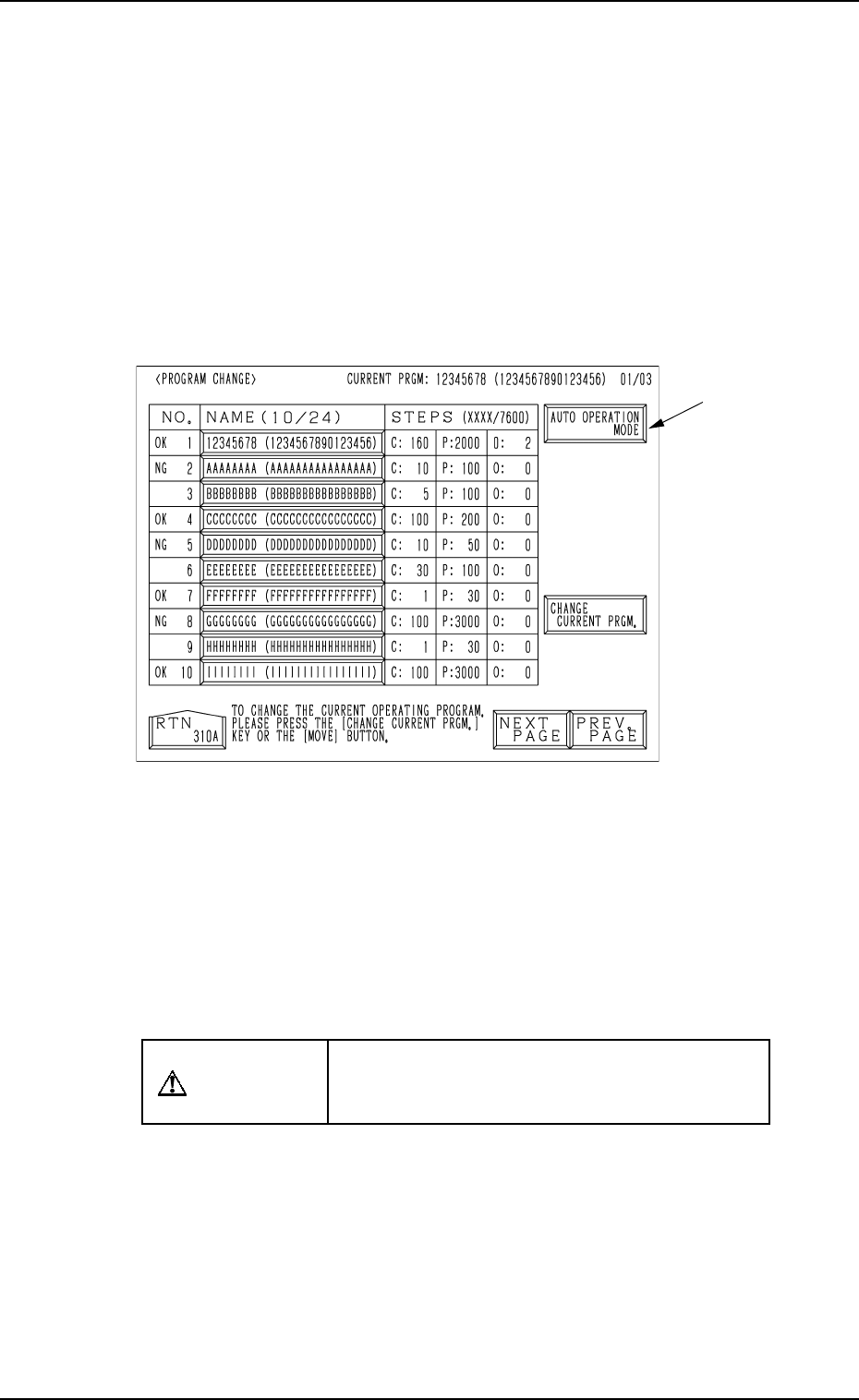
5.2 Program Change Operation
5.2.1 Selection of Current Pattern Program (Program Change)
• Set the current pattern program at the “PROGRAM CHANGE” display.
(Hierarchical Sequence: “AUTO OPN. MODE <PLACEMENT>” Display
→ “AUTO OPN. SUB-MENU” Display → “PROGRAM CHANGE” Display)
This display can be opened from the “MANUAL MODE” display. (Hierarchi-
cal Sequence: “MAIN MENU” Display → “MANUAL MODE” Display)
Note: The menu operations are possible only when the machine is set in the
“STOP” mode.
0004-002 2-33 Tg0246-PM-OP
Fig. 2.21
Ref.: When the [AUTO OPERATION MODE] key A is pressed, the “AUTO
OPN MODE (PLACEMENT)” display opens directly.
Operation Procedure
(1) Set the [OPERATION/SET UP] switch to the “SET UP” side.
(2) Open the maintenance/supply cover and remove the P.C.B. support pins.
CAUTION
Power is kept “ON”! Perform the adjustment
carefully, protecting your hands from moving
mechanisms.
(3) Close the maintenance/supply cover and set the [OPERATION/SET UP]
switch to the “OPERATION” side.
(4) Open the “AUTO OPN. MODE <PLACEMENT>” display and check
the origin marks “”.
(5) Check that “” appears before all devices except “INPUT MACHINE”.
• If “” does not appear before all devices expect “INPUT MACHINE”,
proceed to Step (6).
• If “” appears before all devices expect “INPUT MACHINE”, pro-
ceed to Step (7).
A