1OM-1064-002.pdf - 第200页
5. Operation Mode 5.6 COMPONENT MISSING CHECK MODE Display • This display allows the operator to determine whether or not the component missing check mode should be enabled or disabled. When the [COMP . MISSING CHECK MOD…
5. Operation Mode
“ENABLE/DISABLE”
“ENABLE EXIST”
Set this when there still exist some components in the feeder installed
on the destination feeder slot (FDR. NO.) for alternate use.
Note: Although “DISABLE EMPTY” can also be set, be sure to set
“ENABLE EXIST” when the feeder is replenished with com-
ponents.
“DISABLE EMPTY”
This is automatically set for the feeder Nos. when a component short-
age error is detected.
Notes: (a) “DISABLE EMPTY” can be set only when two or more
feeders are linked.
(b) In the case of an unlinked feeder slot No. (feeder slot No.
for which the alternate feeder mode is not specified), the
“ALTERNATE FEEDER LINK LIST” display can be
opened but “ENABLE EXIST” or “DISABLE EMPTY”
cannot be specified for the feeder slot No.
(c) The parameters “ENABLE EXIST” and “DISABLE
EMPTY” are retained (saved in memory) after “POWER
OFF” or “System Clear” operation is performed.
(d) When the program change operation is performed and
the component data is used for the different program,
“ENABLE EXIST” is set for all feeders.
When the program change operation is performed and
the component data is used for the same program, no
change is made in the “ENABLE/DISABLE” settings.
[ALL FDR. EXIST] Key
When this key is selected and the [SET] key is pressed, “ENABLE
EXIST” is set for all linked feeders where components of the same type
are provided.
Operation Procedure (Using the Alternate Feeder Function)
(1) Confirm that “ENABLE” is set in the “ALTERNATE FEEDER
MODE” text box.
When “DISABLE” is specified in the text box, set “ON” in the
“MODE” data field of the label “ALTERNATE FEEDER” at the
“COMPONENT DATA EDIT” display. (Hierarchical Sequence:
“DATA EDIT” Display → “PATTERN PROGRAM” Display →
“PATTERN PROGRAM EDIT” Display → “COMPONENT DATA”
Display → “COMPONENT DATA EDIT” Display)
(2) Set “ENABLE” in the “INDV. FDR. ENABLE/DISABLE” data box.
(3) Set “SUPPLY PRI” or “EP DATA” in the “ALTERNATE OPERA-
TION” data box.
(4) Press the [INDV. FDR. ENABLE/DISABLE] key. The “INDIVIDUAL
FDR ENABLE/DISABLE” display appears on the screen.
(5) Select the feeder No. keys for which the alternate feeder mode should
be set. The “ALTERNATE FEEDER LINK LIST” display appears
on the screen.
(6) Move the line cursor to the feeder No. for which the alternate mode
should be designated and set “ENABLE EXIST” for the feeder No.
Ref.: When the [ALL FDR. EXIST] key is selected and the [SET]
key is pressed, “ENABLE EXIST” is set for all linked feed-
ers where components of the same type are provided.
0004-002 3-30 Tg0246-PM-OP
5. Operation Mode
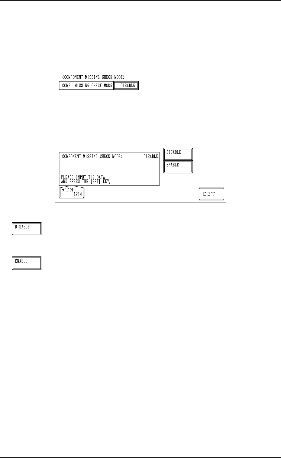
5.6 COMPONENT MISSING CHECK MODE Display
• This display allows the operator to determine whether or not the component
missing check mode should be enabled or disabled.
When the [COMP. MISSING CHECK MODE] key is pressed at the “OPERA-
TION MODE” display, the following display appears on the screen.
0004-002 3-31 Tg0246-PM-OP
Fig. 3.15
[DISABLE] Key
When this key is selected, “DISABLE” is set in the “COMP.
MISSING CHECK MODE” data box, indicating that the com-
ponent missing check mode is disabled.
[ENABLE] Key
When this key is selected, “ENABLE” is set in the “COMP.
MISSING CHECK MODE” data box, indicating that the com-
ponent missing check mode is enabled.
6. RECOVERY OPN. TEACHING OPN. Display
9910-001 3-32 Tg0246-PM-OP
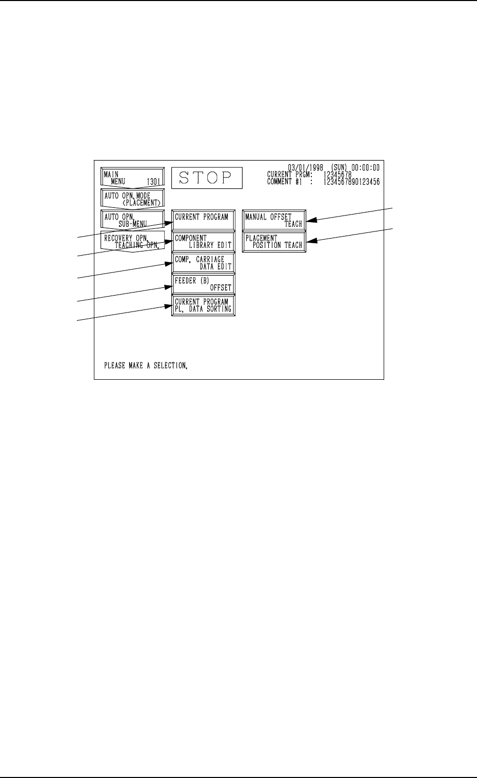
6. RECOVERY OPN. TEACHING OPN. Display
Menus are provided to edit or correct pattern program data, edit component
library data, change the feeding angle of a packaged component, and check
feeder (B) offset data.
When the [RECOVERY OPN TEACHING OPN] key is pressed at the “AUTO
OPN. SUB-MENU” display, the following display appears on the screen.
Note: The -marked items are optional.
Fig. 3.16
*1 [CURRENT PROGRAM] Key
When this key is pressed, the “PATTERN PROGRAM EDIT” display ap-
pears on the screen, enabling the correction and editing of the current pat-
tern program data.
*2 [COMPONENT LIBRARY EDIT] Key
When this key is pressed, the “COMPONENT LIBRARY” display ap-
pears on the screen, enabling the correction of the component library data.
*3 [COMP. CARRIAGE DATA EDIT] Key
When this key is pressed, the “COMPONENT CARRIAGE DATA EDIT”
display appears, enabling the alteration of the component carriage data. When
component packaged equally cannot be prepared for component replenish-
ment and components of the same type but packaged differently in direction
or packaging type (Example: a packaging type changed from a paper to an
embossed tape) must be supplied, this function enables the continuous op-
eration temporarily after replenishment of such components.
*4 [FEEDER (B) OFFSET] Key
When this key is pressed, the “FEEDER (B) OFFSET” display appears on
the screen, enabling the confirmation and editing of the feeder (B) offset
data. This is the same display which appears when the [FEEDER (B) OFF-
SET] key is selected at the “OFFSET DATA” display (the display located
hierarchically below the “DATA EDIT” display).
*1
*2
*3
*4
*5