1OM-1064-002.pdf - 第234页
First Page Fig. 4.1 1-1 Fig. 4.1 1-2 Second Page 8. Manual T ransfer Operation When the [MANUAL TRANSFER OPERA TION] key is pressed at the “MANUAL MODE” display , the following display (Fig. 4.1 1-1) appears on the s…
7. Manual Axis Operation
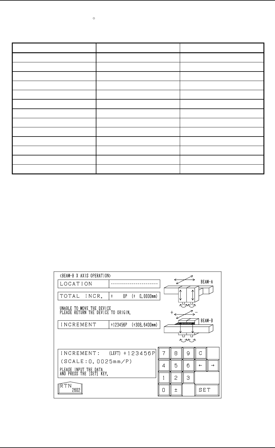
• When data is entered in the “INCREMENT” text box, using the unit “mm”
(distance) or “
” (angle), the scale to be used appears in the data field
beside the ten-key pad.
9910-001 4-17 Tg0246-PM-OP
Device Name Displayed Scale Data Input Range
Beam-A X Axis 0.0025 mm / p
± 999999(P)
Beam-A Y Axis 0.0025 mm / p
± 999999(P)
Beam-A Up/Down Axis (Left) 0.0025mm / p
± 99999(P)
Beam-A Up/Down Axis (Right) 0.0025 mm / p
± 99999(P)
Beam-A Rotation Axis (Left)
0.9°/ 128 p ± 99999(P)
Beam-A Rotation Axis (Right)
0.9°/ 128 p ± 99999(P)
Beam-B X Axis 0.0025 mm / p
± 999999(P)
Beam-B Y Axis 0.0025 mm / p
± 999999(P)
Beam-B Up/Down Axis (Left) 0.0025 mm / p
± 99999(P)
Beam-B Up/Down Axis (Right) 0.0025 mm / p
± 99999(P)
Beam-B Rotation Axis (Left)
0.9°/ 128 p ± 99999(P)
Beam-B Rotation Axis (Right)
0.9°/ 128 p ± 99999(P)
Backup Up/Down Axis 0.005 mm / p
± 99999(P)
• Enter data in the “TOTAL INCR.” text box according to the resolution
(scale) of each individual devices and press the [SET] key.
When the [MOVE] button is pressed, the selected device moves as far
as the set value and stops.
Note: When the current position of the selected device is indefinite, “---
-----” appears in the “LOCATION” text box at the manual axis op-
eration display. (Fig. 4.10)
Zero the device first and then perform the manual axis operation
for the selected device.
Table 4.1
Fig. 4.10
First Page
Fig. 4.11-1
Fig. 4.11-2
Second Page
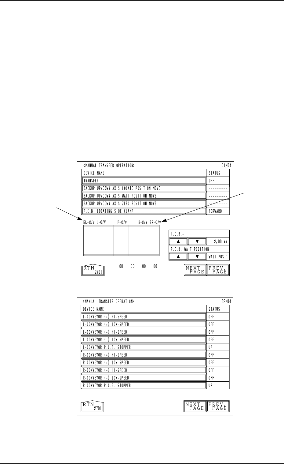
8. Manual Transfer Operation
When the [MANUAL TRANSFER OPERATION] key is pressed at the
“MANUAL MODE” display, the following display (Fig. 4.11-1) appears on
the screen.
Every time the [NEXT PAGE] or the [PREV. PAGE] key is pressed, another or
previous page appears on the screen.
This display enables the manual P.C.B. input and output operations and the
cycle operation of each individual conveyors and P.C.B. stoppers.
Notes: (a) These keys can be selected only when the machine is in the “STOP”
mode.
(b) The -marked functions are optional.
(c) The fourth page appears only when the machine is equipped with
the optional device.
This page does not appear when a standard machine is used.
8. Manual Transfer Operation
9910-001 4-18 Tg0246-PM-OP
First Page
A P.C.B. can be transferred manually and the backup base can be cycle-oper-
ated.
[TRANSFER] Key
When this key is selected and the [MOVE] button is pressed, a P.C.B. can
be transferred or discharged.
When there is a P.C.B. on the input conveyor, it is transferred onto the P
conveyor. When a P.C.B. is located on the P conveyor, it is discharged to
the output conveyor.
When there are P.C.B.’s on both the input and P conveyors, both transfer
and discharge actions take place in succession.
[BACKUP UP/DOWN AXIS LOCATE POSITION MOVE] Key
When this key is selected and the [MOVE] button is pressed, the backup
base moves to the positioning place.
[BACKUP UP/DOWN AXIS WAIT POSITION MOVE] Key
When this key is selected and the [MOVE] button is pressed, the backup
base moves to the standby position.
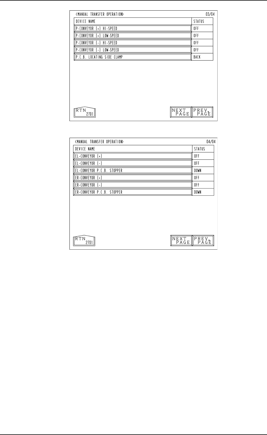
Fig. 4.11-3
Fig. 4.11-4
Fourth Page
(Option)
Third Page
8. Manual Transfer Operation
9910-001 4-19 Tg0246-PM-OP