1OM-1064-002.pdf - 第153页
6. Starting, Emergency Stop, and T emporary Stop (Pause) Operations for Automatic Operation (“PLACE” Mode) T o supply components whenever necessary In the following cases, components can be supplied through the procedure…
6. Starting, Emergency Stop, and Temporary Stop (Pause) Operations for Automatic Operation (“PLACE” Mode)
Fig. 2.33
Fig. 2.34
Fig. 2.35
Fig. 2.36
Fig. 2.37
Fig. 2.38
Fig. 2.39
6.4.3 Multi-Layer Tray Feeders (Option)
To supply components when a component shortage error has occurred
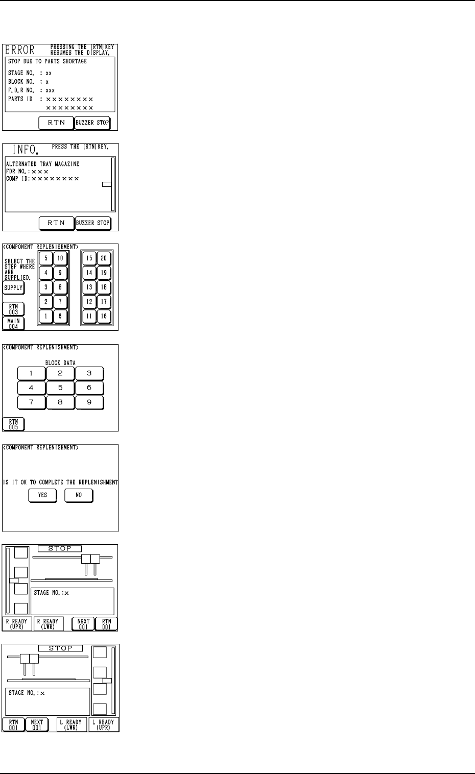
(1) When a component shortage error occurs, or the magazine alternate
function is activated, the magazine in short of components moves to
the set-up position and is separated from the elevator shaft. In this
case, the “ERROR” display (Fig. 2.33) or the “INFO.” display (Fig.
2.34) appears on the operation monitor.
Check the contents of the described items.
(2) Press the [BUZZER STOP] key.
The buzzer stops.
(3) Press the [RTN] key. The display (Fig. 2.35) appears on the screen.
(4) Check the stage (pallet) and the block which caused a component
shortage error.
When a block is specified, press the No. key of the stage where a
component shortage error has occurred. The display (Fig. 2.36) ap-
pears on the screen, enabling you to check the block data.
(5) Open the upper or the lower door and then the magazine door.
(6) Pull out the pallet on the stage in short of components and load it
with components.
When several stages and blocks are short of components, load all
pallets with components.
(7) Press the No. key of the stage in red (ON or flickering) at the display
(Fig. 2.35) and the No. key of the block in red (ON or flickering) at
the display (Fig. 2.36). The keys turn violet.
(8) Confirm that all components are supplied completely and close all
doors (magazine, upper and lower doors).
(9) Press the [SUPPLY] key at the display (Fig. 2.35).
The display (Fig. 2.37) appears on the screen.
(10) Confirm that components are supplied completely and press the [YES]
key to declare the completion of component replenishment.
Pressing the [NO] key resumes the display (Fig. 2.35).
(11) Press the [U READY] or [L READY] button on the side of the multi-
layer tray feeder. The door is locked and the machine can be operated
with the feeder connected.
(12) Re-start the operation.
• When the machine is in the automatic operation mode, the opera-
tion re-starts automatically.
• When the machine is in the “PAUSE” mode, press the [START]
button on the main body side to re-start the operation.
Ref.: (a) When several pallets are short of components, follow Step
(7) every time components are supplied or another step (col-
lective operation) after all components are supplied.
(b) It is also possible to replenish the tray in the middle of pro-
cessing with components or replace it with another one. In
this case, it is required to update the tray matrix.
Refer to “7. Tray Pick-Up Matrix of Section 3” or “ 6.4 Ma-
trix Change Operations of Section 2” in the instruction manual
of the multi-layer tray feeders for details.
0103-003 2-54 Tg0246-PM-OP

6. Starting, Emergency Stop, and Temporary Stop (Pause) Operations for Automatic Operation (“PLACE” Mode)
To supply components whenever necessary
In the following cases, components can be supplied through the procedure
below.
• Follow the procedure below to supply components before re-starting the
operation when the machine has stopped due to a stage or a tray in short of
components.
• Follow the procedure below to supply components after a set-up operation
is performed.
(1) Press the [STOP] button to stop the machine.
(2) Open the “ELEVATOR UNIT” display. (Hierarchical Sequence: “LO-
CAL MODE” Display → “MANUAL MODE” Display → “ELEVATOR
UNIT” Display)
Select the [UPPER MAGAZINE CONNECT/DISCON] or the [LOWER
MAGAZINE CONNECT/DISCON] key and press the [MOVE] button
to separate the pertinent magazine from the elevator shaft.
(3) Open the “COMPONENT REPLENISHMENT” display (Fig. 2.35).
(4) Check the stage (pallet) and the block which caused a component short-
age error.
When a block is specified, press the No. key of the stage where a compo-
nent shortage error has occurred. The display (Fig. 2.36) appears on the
screen, enabling you to check the block data.
(5) Press the [X READY (LWR)] or the [X READY (UPR)] key of the feeder
unit where components should be supplied. “X” represents either “L” or
“R”.
The upper or the lower door is unlocked.
(6) Open the upper or the lower door and then the magazine door.
(7) Pull out the pallet on the stage where components should be supplied and
load it with components.
(8) Press the No. key of the stage in red (ON or flickering) at the display (Fig.
2.35) and the No. key of the block in red (ON or flickering) at the display
(Fig. 2.36). The keys turn violet.
(9) Confirm that all components are supplied completely and close all doors
(magazine, upper and lower doors).
(10) Press the [SUPPLY] key at the display (Fig. 2.35).
The display (Fig. 2.37) appears on the screen.
(11) Confirm that components are supplied completely and press the [YES]
key to declare the completion of component replenishment.
Pressing the [NO] key resumes the display (Fig. 2.35).
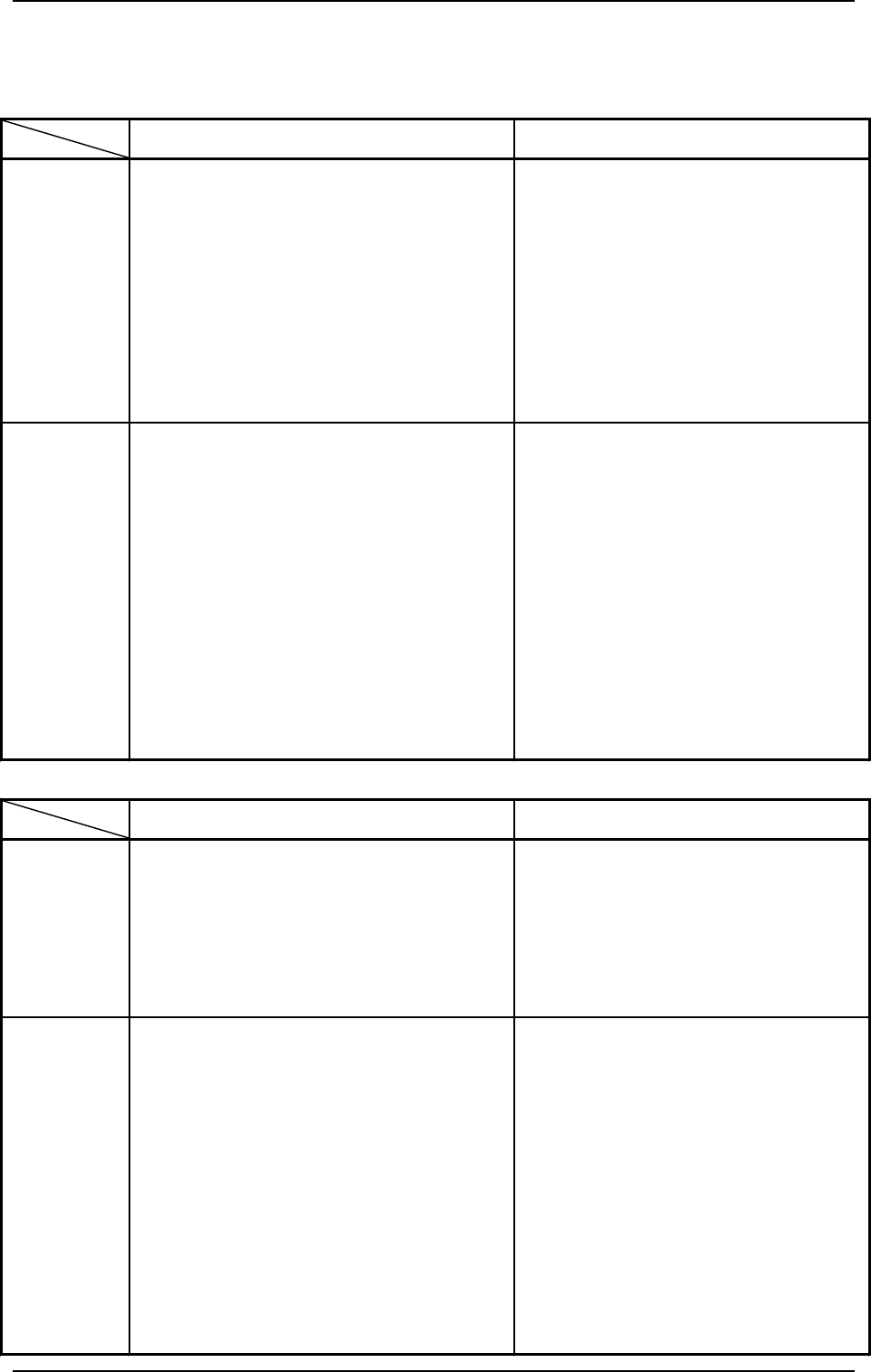
(12) Press the [L READY (LWR)] or the [L READY (UPR)] key when the
multi-layer tray feeder on the left side is ready. When the feeder on the
right side is ready, press the [R READY (LWR)] or the [R READY (UPR)]
key.
The door on the related side is locked, making it possible to operate the
machine with the feeder being connected.
Ref.: (a) When several pallets are short of components, follow Step (8) ev-
ery time components are supplied or another step (collective op-
eration) after all components are supplied.
(b) It is also possible to replenish the tray in the middle of processing
with components or replace it with another one. In this case, it is
required to update the tray matrix.
Refer to “7. Tray Pick-Up Matrix of Section 3”or “6.4 Matrix
Change Operations of Section 2” in the instruction manual of the
multi-layer tray feeders for details.
0004-002 2-55 Tg0246-PM-OP
6. Starting, Emergency Stop, and Temporary Stop (Pause) Operations for Automatic Operation (“PLACE” Mode)
6.5 Operational Displays during Automatic Operation
Automatic Operation Sub-Menu
RUN/WAIT PAUSE
Possible
Operations
•
Editing and Save Operation of Recalled
Data (Recalled Messages)
• RECALL DEVICE ERROR
• RECALL HANDLING ERROR
• RECALL MACHINE INFO
• RECALL COMP. RECOG. ERROR
•
Editing and Save Operation of Management
Data
•
Operation Mode
•
Recovery Operation
•
Teaching Operation
•
Change of Carrier Data
•
Feeder (B) Offset
•
Editing and Save Operation of Recalled
Data (Recalled Messages)
•
Editing and Save Operation of Management
Data
•
Editing and Save Operation of Tray Pick-
Up Matrix Data (Option)
Impossible
Operations
•
Semi-Automatic Operation (Full Auto Step)
•
Save Operation of Operation Mode
•
Save Operation of Recovery/Teaching
Operation Data
•
Editing and Save Operation of Recalled Data
(Recalled Messages)
• Recalled Recognition Error Image
•
Editing and Save Operation of Tray Pick-Up
Matrix Data (Option)
•
Shift to the “PRODUCT CHANGE” Display
•
Shift to the “PROGRAM CHANGE” Display
•
Shift to the “PICK-UP LOCATION” Display
•
Semi-Automatic Operation (Full Auto Step)
•
Save Operation of Recovery/Teaching
Operation Data
• Correction of Current Program
• Correction of Component Library Data
•
Shift to the “PRODUCT CHANGE”
Display
•
Shift to the “PROGRAM CHANGE”
Display
•
Shift to the “PICK-UP LOCATION”
Display
RUN/WAIT PAUSE
Possible
Operations
•
Zeroing Operation
•
Manual Subsystem Operation
•
Manual Axis Operation
•
Manual Transfer Operation
Impossible
Operations
•
Shift to the “PROGRAM CHANGE” Display
•
Shift to the “PRODUCT CHANGE” Display
•
Shift to the “ZEROING OPERATION” Display
•
Shift to the “MANUAL SUBSYSTEM
OPERATION” Display
•
Shift to the “MANUAL AXIS OPERATION”
Display
•
Shift to the “MANUAL NOZZLE CHANGE
OPERATION” Display
•
Shift to the “MANUAL TRANSFER
OPERATION” Display
•
Shift to the “PCB SUPPORT PINS SET-UP
MODE” Display
•
Shift to the “PROGRAM CHANGE”
Display
•
Shift to the “PRODUCT CHANGE”
Display
•
Manual Nozzle Change Operation
•
Shift to the “PCB SUPPORT PINS SET-
UP MODE” Display
Manual Mode
9910-001 2-56 Tg0246-PM-OP