1OM-1064-002.pdf - 第197页
5. Operation Mode When the [INDV . FDR. ENABLE/DISABLE] key is pressed at the “AL TER- NA TE MODE” display , the display (Fig. 3.13) appears on the screen. • This display allows the operator to check how the alternate fe…
5. Operation Mode
[ENABLE] or [DISABLE] Key
[ENABLE] Key
Select this key to use the alternate feeder mode.
[DISABLE] Key
Select this key not to use the alternate feeder mode.
Note: When “DISABLE” is set, the subsequent alternate
feeder operation is prohibited.
“ALTERNATE OPERATION”
[SUPPLY PRI] Key
Select this key to immediately alternate the feeder to the
one for component replenishment.
[EP DATA]
Select this key to pick up components continuously from
the currently selected feeder.
9910-001 3-27 Tg0246-PM-OP
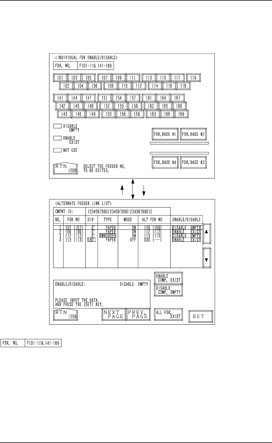
5. Operation Mode
When the [INDV. FDR. ENABLE/DISABLE] key is pressed at the “ALTER-
NATE MODE” display, the display (Fig. 3.13) appears on the screen.
• This display allows the operator to check how the alternate feeder function
is working (feeder status) and the completed feeder replenishment can be
inputted.
[107][RTN]
Fig. 3.13
Fig. 3.14
9910-001 3-28 Tg0246-PM-OP
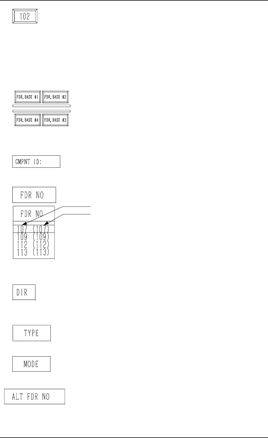
“FDR NO.”
Displayed are the Nos. of the feeders which can be selected.
The feeder Nos. change, depending on which key ([FDR.
BASE #1], [FDR. BASE #2], [FDR. BASE #3], or [FDR.
BASE #4] key) is selected.
5. Operation Mode
Feeder No. Keys
These keys are labeled with feeder Nos.
The keys are also color-coded, indicating how the alternate
feeder function is working.
Pink : DISABLE EMPTY
Light Green : ENABLE EXIST
Dark Gray : NOT USED
Pressing each key opens the “ALTERNATE FEEDER LINK
LIST” display (Fig. 3.14).
[FDR. BASE #1], [FDR. BASE #2], [FDR. BASE #3], and
[FDR. BASE #4] Keys
When one of these keys is selected, the feeder No. keys allo-
cated to the selected feeder base appear in the display, en-
abling the operator to designate the desired feeder Nos. to
check how the alternate function is working on the selected
feeders.
“CMPNT ID:”
Displayed is the component ID which is allocated to the se-
lected feeder No.
“FDR NO”
Displayed are the selected feeder Nos.
• This shows the feeder No. of the component data.
• This shows the actual feeder No.
This indicates the feeder Nos. where component No. off-
set (reserved data) specified in the operation data is added.
In the left figure (an example), “+0” is set as component
No. offset.
Note: “---” appears in the “FDR NO” data field, indi-
cating the no feeder can be installed for the slot
No.
“DIR”
Displayed are the directions specified in the component li-
brary data. Components are supplied in the specified direc-
tions.
“TYPE”
Displayed are the types of components specified in the com-
ponent library data.
“MODE”
Displayed are the modes (ON or OFF) specified for “AL-
TERNATE FDR.” in the component data.
“ALT FDR NO”
Displayed is the destination feeder No. for alternate use of
the selected feeder No.
9910-001 3-29 Tg0246-PM-OP