1OM-1064-002.pdf - 第173页
2. AUTO OPN MODE (PLACEMENT) Display *12 [SCREENS] Key When this key is pressed, the information in “ORIGIN MONITOR” *14 changes. *13 [LOCK] and [UNLOCK] Each pressing of this key locks and unlocks the indication on the …
2. AUTO OPN MODE (PLACEMENT) Display
DEVICE TESTDEVICE TEST
(PLACEMENT)
(
PASSAGE
)
9910-001 3-4 Tg0246-PM-OP
*6 Normally the key is labeled as follows.
CAUTION
Do not perform automatic operation when the
key is labeled as “DEVICE TEST (PLACE-
MENT)” or “DEVICE TEST (PASSAGE)”.
Normal automatic operation cannot be per-
formed because test mode data is set.
“(PLACEMENT)” or “(PASSAGE)” simply shows the status of the vacuum
pump.
(PLACEMENT) : Vacuum Pump ON
(PASSAGE) : Vacuum Pump OFF
*7 The number of produced P.C.B.’s is counted for both single- and multi-
unit P.C.B.’s when specified in the pattern program data.
Single-Unit P.C.B. : Normally the counter counts up in increments of
one P.C.B. in the pattern program data and the re-
petitive pattern program data.
Multi-Unit P.C.B. : The counter counts up the number of unit P.C.B.’s
where components are actually placed.
Example:
*8 This section displays the time required to finish one P.C.B. excluding the
P.C.B. in the middle of process.
This is the total time from the P.C.B. transfer start until the X/Y beam is
zeroed after the completion of the last component placement.
*9 [CLEAR THE P.C.B. COUNTER] Key
This key is used to clear the P.C.B. counter *7 to “0” (zero).
*10 This section displays information on machine status.
*11 [AUTO OPN SUB-MENU] Key
This key is used to call the operation and function menus required for
automatic operation.
AUTO OPN MODE
(
PLACEMENT
)
AUTO OPN MODE
(
PASSAGE
)
NG
NG
The counter reads the following when the
P.C.B. described on the left is processed.
Single-Unit P.C.B. : +1
Multi-Unit P.C.B. : +12 - 2 (defective
P.C.B.’s) = +10
2. AUTO OPN MODE (PLACEMENT) Display
*12 [SCREENS] Key
When this key is pressed, the information in “ORIGIN MONITOR” *14
changes.
*13 [LOCK] and [UNLOCK]
Each pressing of this key locks and unlocks the indication on the box
shown as *13.
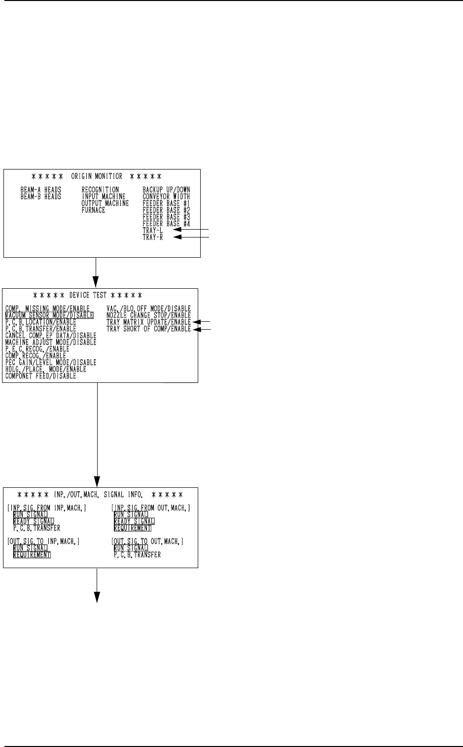
*14 Monitor Information under Automatic Operation
Every time the [SCREENS] key *12 is pressed, the information in the
monitor box changes.
• ORIGIN MONITOR
Devices located at their origins are marked
with “”.
Note: The -marked items are optional.
• DEVICE TEST
Displayed in the monitor box are param-
eters set as test mode data.
(Not used in normal cases)
Notes:
(a) As long as each parameter is set
to establish the placement mode,
this display does not appear on the
screen, regardless of the param-
eter (either “ENABLE” or “DIS-
ABLE”) set in the “DRY CYCLE
MODE” data box at the “TEST
MODE” display.
(b) The -marked items are optional.
• INP./OUT.MACH. SIGNAL INFO.
Signal exchanges (ON/OFF status) be-
tween the main and input or output ma-
chines are displayed at real time.
When a signal is ON, the background color
of the signal indicator section turns green.
This function can be used to check the sig-
nal system at the system connection.
0103-003 3-5 Tg0246-PM-OP
[SCREENS] Key
[SCREENS] Key
[SCREENS] Key
2. AUTO OPN MODE (PLACEMENT) Display
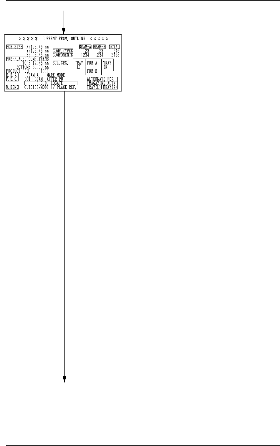
• CURRENT PRGM. OUTLINE
The outline of the current pattern program
data is displayed.
“PCB SIZE X, Y, Z”
Parameters set in the operation data are
displayed.
“PRE-PLACED COMP. THKNS”
Parameters set in the operation data are
displayed.
“PRODUCT PCB”
The actual number of multi-unit
P.C.B.’s is displayed.
This appears only when a repetitive
pattern program is used.
“B.B.R.”
This appears when the bad board re-
ject function (option) is used.
“P.E.C.”
This appears when the P.E.C. recogni-
tion function is used.
“P.C.B. LOCATE”
The P.C.B. locating information set on
the operation data or in the input/out-
put mode, is indicated.
“V. BEND
When the V. bend detection function
is added, this is indicated.
“COMP. TYPES”
The number of different component
IDs specified in the component data is
displayed.
When component types are set on two
or more feeders using the same com-
ponent ID names, the number of the
component types is regarded as one
type.
“COMPONENTS”
The number of components to actually
be placed is displayed.
When “S” (Skip) or “C” (Cancel) is set
as a control command, the component
of the step is not included in “COM-
PONENTS”.
“SEL. CRG.”
This shows which feeder carriage is
used.
Green : Selected Feeder Carriage
Black : Unselected Feeder Carriage
[SCREENS] Key
[SCREENS] Key
0103-003 3-6 Tg0246-PM-OP