1OM-1064-002.pdf - 第91页
Feeder Nos. (FDR NO) The numerals show feeder Nos. 7. Construction of Feeder Carriages 0004-002 1-61 Tg0246-PM-OP 701 to 799 801 to 899 FDR No. 101 to 139 Beam A Side Beam B Side (Front Side of Machine) Multi-Layer Tray …

7. Construction of Feeder Carriages
9910-001 1-60 Tg0246-PM-OP
(2) Stick Feeder (Vibratory)
Max. 12 feeders (when only vibratory stick feeders are installed)
One vibratory stick feeder occupies six feeder slot Nos. (lanes).
The following shows the feeder slot Nos. (lanes) for which vibratory stick
feeder units can be registered.
Table 1.8
(3) Tray Feeders
Max. 2 Feeders (Up to 360 types can be used)
Ref.: Tray feeders do not give any effect to the number of installable
tape and stick feeders.
Note: The number of installable feeders varies according to the combination
of tape and stick feeders. Consult our sales personnel for details.
Feeder Base
Nos.
Unit Nos.
Occupied
Lanes
(FDR NO)
Vibratory Stick Feeder Unit #1 101 to 106
Feeder Base #1 Vibratory Stick Feeder Unit #2 107 to 112
Vibratory Stick Feeder Unit #3 113 to 118
Vibratory Stick Feeder Unit #4 121 to 126
Feeder Base #2 Vibratory Stick Feeder Unit #5 127 to 132
Vibratory Stick Feeder Unit #6 133 to 138
Vibratory Stick Feeder Unit #7 201 to 206
Feeder Base #3 Vibratory Stick Feeder Unit #8 207 to 212
Vibratory Stick Feeder Unit #9 213 to 218
Vibratory Stick Feeder Unit #10 221 to 226
Feeder Base #4 Vibratory Stick Feeder Unit #11 227 to 232
Vibratory Stick Feeder Unit #12 233 to 238
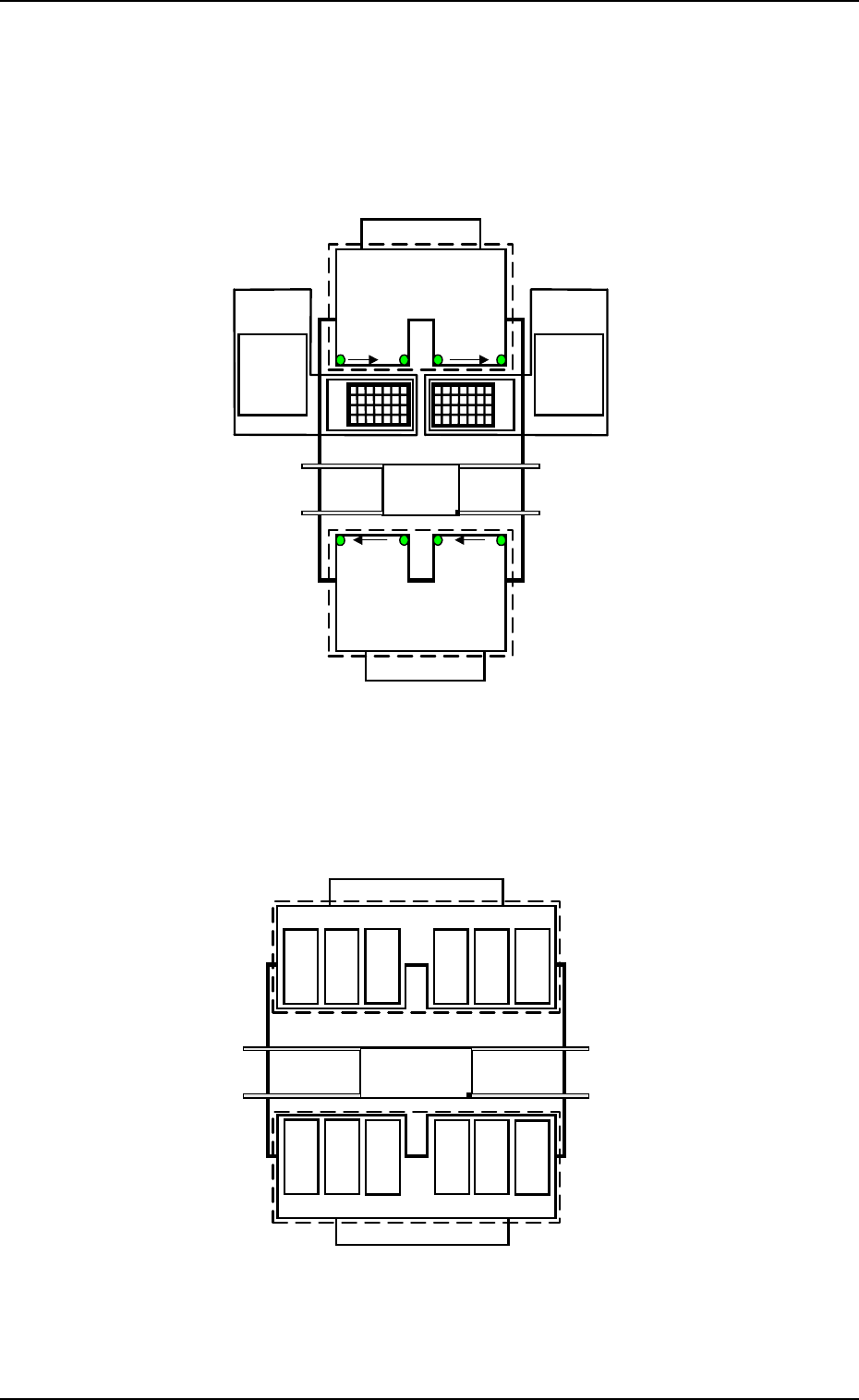
Feeder Nos. (FDR NO)
The numerals show feeder Nos.
7. Construction of Feeder Carriages
0004-002 1-61 Tg0246-PM-OP
701 to799
801 to899
FDR No. 101 to 139
Beam A Side
Beam B Side
(Front Side of Machine)
Multi-Layer
Tray Feeder L
(Option)
601 to699301 to 399
401 to 499
501 to 599
219
…
201
239
…
221
…
139121119
…
101
Feeder
Base
#4
FDR No. 239
to 201
Feeder
Base
#3
Feeder
Base
#1
Feeder
Base
#2
TAPE
Multi-Layer
Tray Feeder R
(Option)
Feeder Base A
Feeder Base B
Fig. 1.27-1
Fig. 1.27-2
141
149
to
Feeder Base
#1
151
159
161
169
171
179
181
189
191
199
261
269
251
259
241
249
291
299
271
279
281
289
Beam A Side
FDR No. 141 to 199
FDR No. 299 to 241
Beam B Side
(Front Side of Machine)
Feeder Base
#2
Feeder Base
#4
Feeder Base #3
VIBRATORY STICK
Feeder Base A
Feeder Base B
to
to
to to
to
to to
to
to to
to
7. Construction of Feeder Carriages
0308-003 1-62 Tg0246-PM-OP
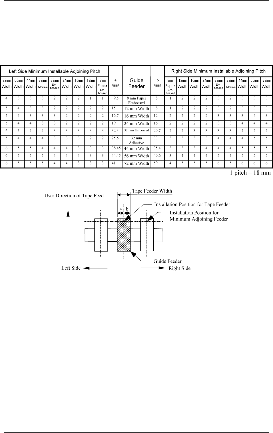
7.1 Feeder Installation on Carriages
Adjoining Pitch for Tape Feeder Installation
(1) Minimum Adjoining Pitch Based on Guide Feeder
Note: Shown in Fig. 1.28 is a view based on the direction in which the feed-
ers are installed.
Table 1.9
Fig. 1.28