1OM-1064-002.pdf - 第191页
5. Operation Mode Operation Procedure (1) Select one of the data boxes A. (2) Select either one of the option keys B and press the [SET] key C. When each data box for speed reduction is selected, a ten- key pad appears. …
5. Operation Mode
B
C
A
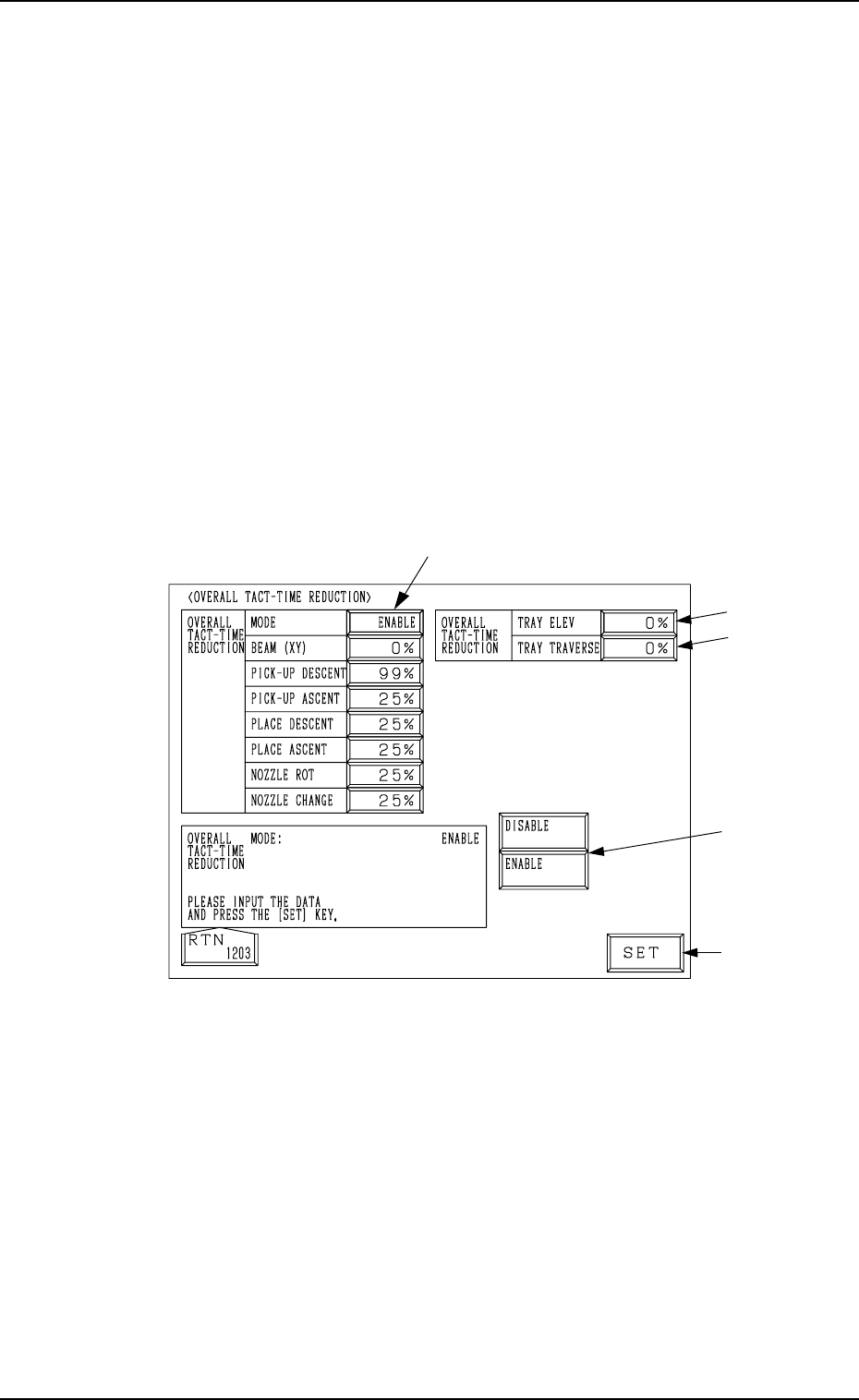
5.2 OVERALL TACT-TIME REDUCTION Display
• The upper limit of the tact time specified in the component library data can
be set in coordination with the working speed of each device (rate of speed
reduction based on the highest speed) specified in the component library
data.
• If a higher speed than that specified here is set in the component library
data, it is regulated to the specified upper limit for all components.
• If a lower speed than the upper limit is set in the component library data, it
becomes valid for such components.
• When there is still some room in the placement tact time according to the
line balance, the machine can be operated at a slow tact time with each
device movement slowed down.
When the [OVERALL TACT TIME REDUCTION] key is pressed at the “OP-
ERATION MODE” display, the following display appears on the screen.
Note: The -marked functions are optional.
Fig. 3.8
0004-002 3-21 Tg0246-PM-OP
5. Operation Mode
Operation Procedure
(1) Select one of the data boxes A.
(2) Select either one of the option keys B and press the [SET]
key C.
When each data box for speed reduction is selected, a ten-
key pad appears. Enter a numeric value using the ten-key
pad and press the [SET] key to specify the rate of speed
reduction.
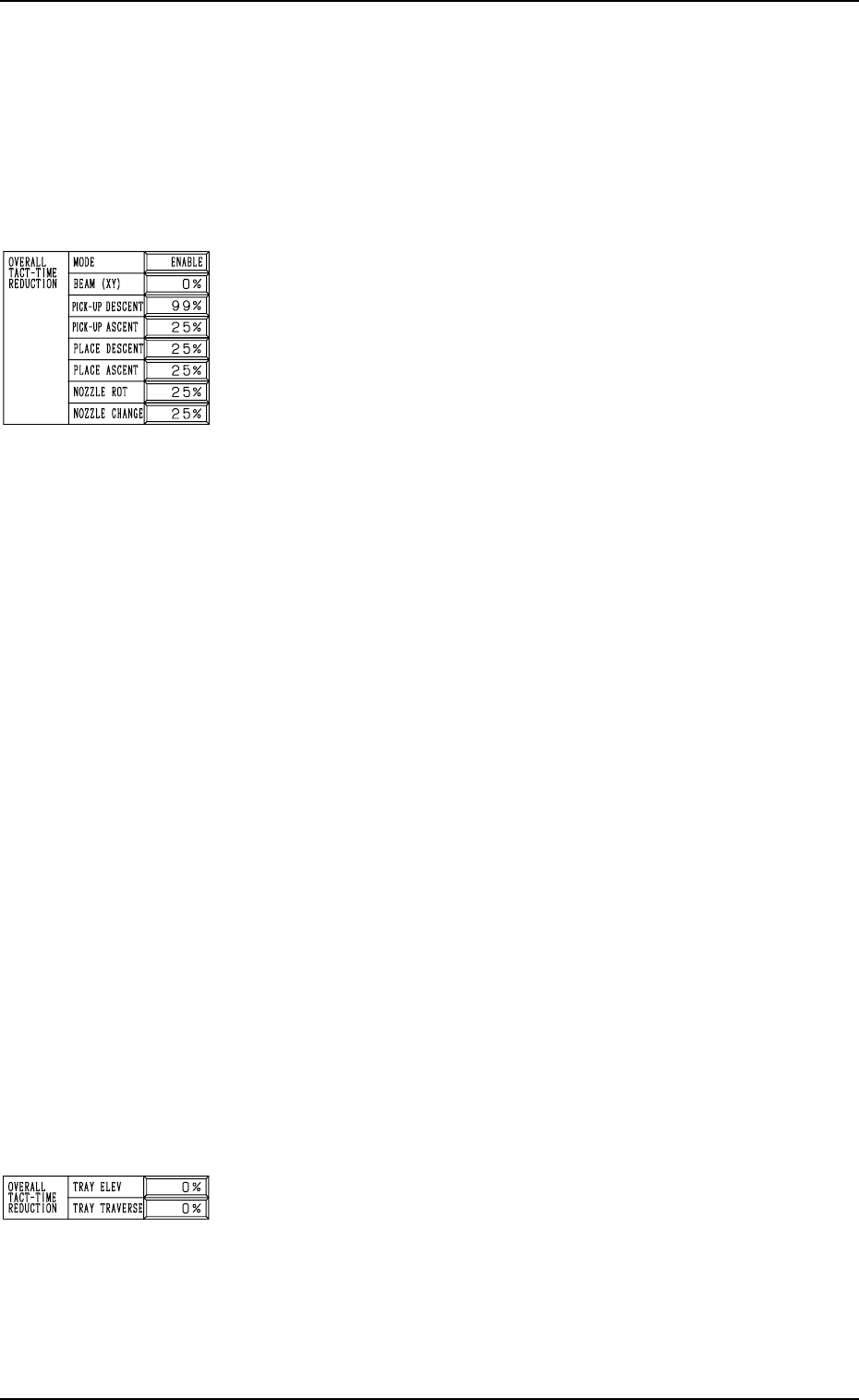
MODE
Set “ENABLE” or “DISABLE” in the data box. When “EN-
ABLE” is set, the set rate of speed reduction for each device
becomes valid.
BEAM (XY)
Set the rate of speed reduction in the data box for the X/Y
beam (Beams A and B).
PICK-UP DESCENT
Set the rate of speed reduction in the data box for the de-
scending movement of the nozzle (nozzle movement to pick
up a component from the feeder).
PICK-UP ASCENT
Set the rate of speed reduction in the data box for the as-
cending movement of the nozzle (nozzle movement after the
nozzle has picked up a component from the feeder).
PLACE DESCENT
Set the rate of speed reduction in the data box for the de-
scending movement of the nozzle (nozzle movement to place
a component on the P.C.B.).
PLACE ASCENT
Set the rate of speed reduction in the data box for the as-
cending movement of the nozzle (nozzle movement after the
nozzle has placed a component on the P.C.B.).
NOZZLE ROT
Set the rate of speed reduction in the data box for the nozzle
rotation.
NOZZLE CHANGE
Set the rate of speed reduction in the data box for a series of
operation performed when the nozzle is changed.
TRAY ELEV (Option)
Set the rate of speed reduction in the data box for the up and
down movement of the multi-layer tray feeder elevator.
TRAY TRAVERSE (Option)
Set the rate of speed reduction in the data box for the pull-
out/pushback actions of the pallet from or to the multi-layer
tray feeder.
0004-002 3-22 Tg0246-PM-OP
5. Operation Mode
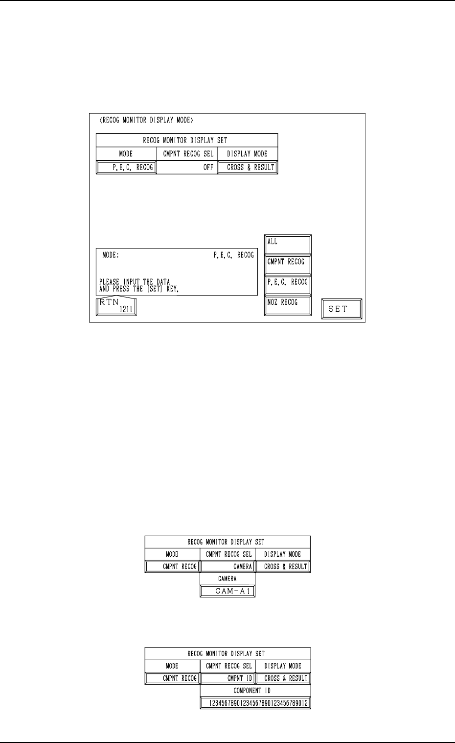
5.3 RECOG MONITOR DISPLAY MODE Display
• It can be specified how to display the results of recognition such as P.E.C.
and component recognition functions on the recognition monitor.
When the [RECOG MONITOR DISPLAY MODE] key is pressed at the “OP-
ERATION MODE” display, the following display appears on the screen.
9910-001 3-23 Tg0246-PM-OP
Fig. 3.9
MODE
Specify the recognition mode which the displayed result should be based
on.
Set “ALL”, “CMPNT RECOG”, “P.E.C. RECOG” or “NOZ RECOG” in
the data box.
CMPNT RECOG SEL
Specify the requirements which the displayed result should be based on
only for the component recognition function.
Set “OFF”, “CAMERA”, “CMPNT ID”, “FEEDER”, “HEAD”, or
“NOZZLE” in the data box.
• When “CAMERA” is set in the data box, specify the camera No.
“CAM-A1”, “CAM-A2”, “CAM-B1”, or “CAM-B2”.
Fig. 3.10-1
• When “CMPNT ID” is set in the data box, specify the component ID.
Fig. 3.10-2